Threading tools · toolholders and inserts
In turning, a spoiled size can be saved by the next pass. In threading every pass follows the same helical track: if the edge sits wrong or the insert shifts in its pocket by a hundredth, the profile is spoiled for good — and by that point the part has already been through every earlier operation. So in a threading assembly exactly one thing matters: whether the insert is in the same place on the tenth pass as it was on the first.
We reply within the working day. There is no minimum order.
The main decision
A threading insert is always triangular and is always held by a screw through the central hole — and there the designer's freedom ends. The difference between the series lies elsewhere: whether there is a replaceable shim under the insert and whether there is a clamp above it. Those two answers give four families: ME and KE for external threads, MI and KI for internal ones.
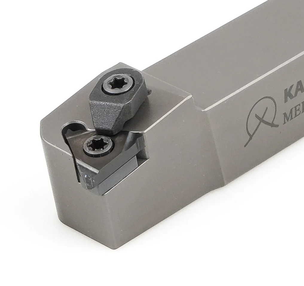
ME External threads, screw and clampThe insert is drawn down by a Torx screw straight into the pocket in the body. In the version with the index C a heavy clamp is fitted above it as well.
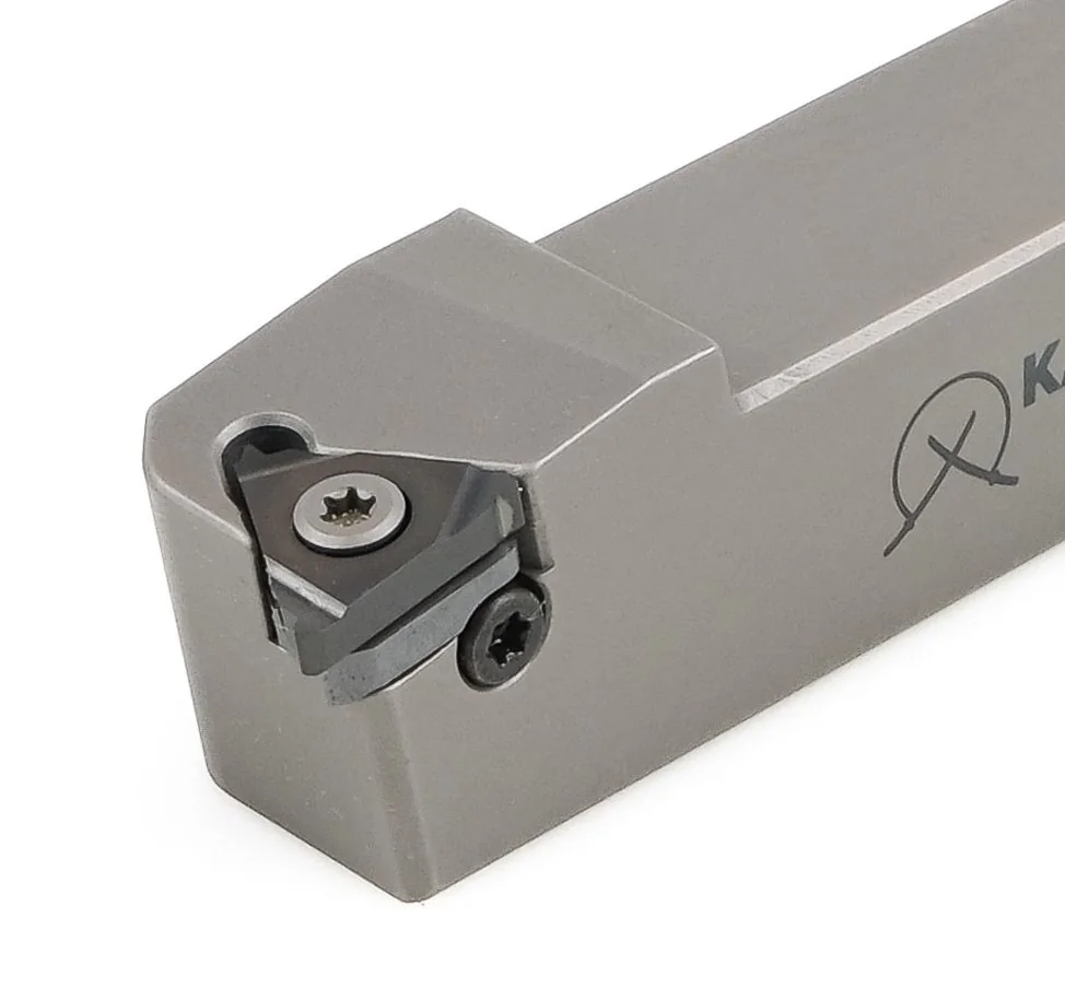
KE External threads, with a shimA separate hard shim on its own screw sits under the cutting insert. The assembly has one more part — and lasts one part longer.
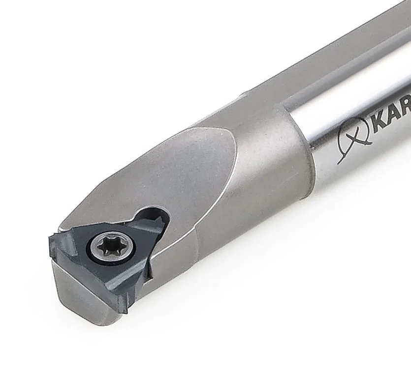
MI Internal threads, compact headThe insert sits in the pocket on a single screw. The head of the bar comes out narrower than the shank itself — which is exactly what lets it into a small hole.
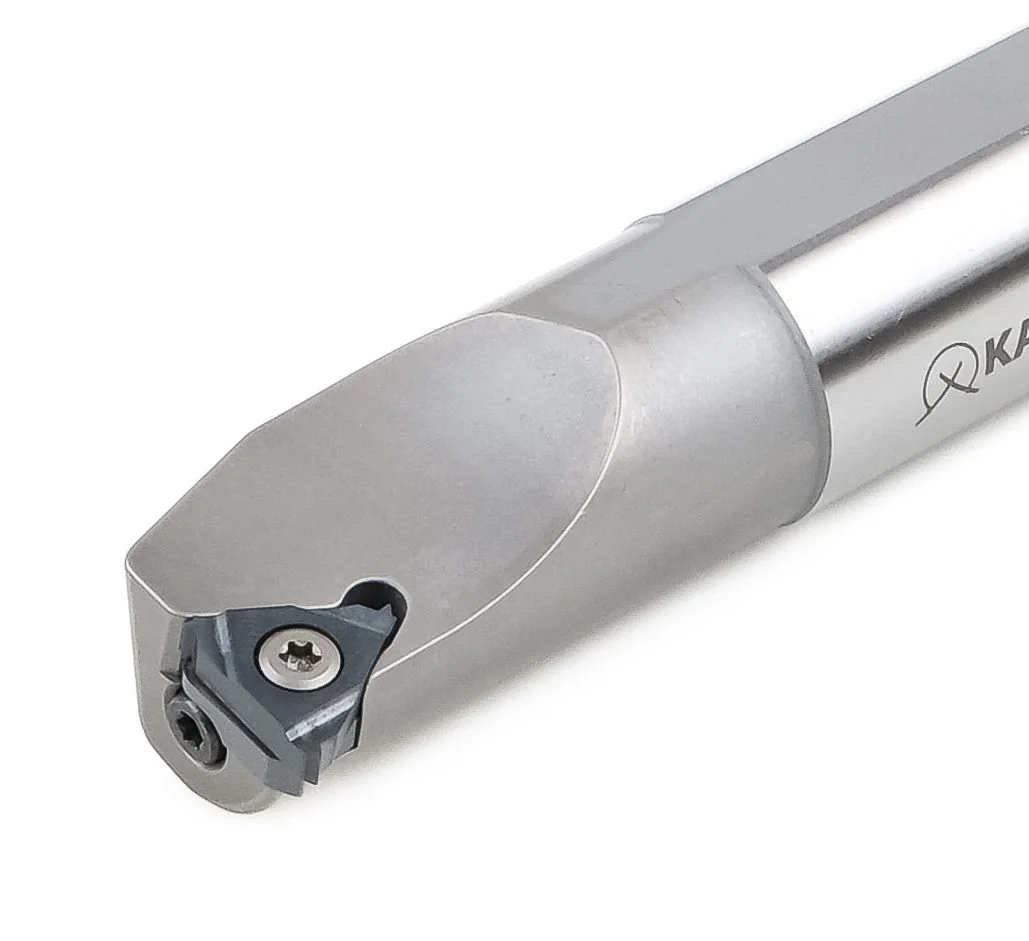
KI Internal threads, with a shimThe same principle as the KE but in a boring bar: a replaceable shim takes what would otherwise beat out the pocket.
What follows from that. The M series means the fewest parts in the assembly: a smaller head, a lower cost of a mistake at an edge change, access into tight places. The K series means a replaceable shim: in production work it is the shim that wears while the body stays serviceable. In the small sizes there is no choice — only M is available there. From the 16×16 shank and the Ø25 bar upwards a choice appears, and it is decided not by the part material but by the number of parts in the batch.
Selection table
With threading tools you do not order “a toolholder” and “an insert” but a set: the body, the insert profile and the grade are tied together more tightly than in any other operation. The table reads from left to right — from the line on the drawing to three items on the order.
| Thread on the drawing | Toolholder | Insert | Grade | What to take into account |
|---|---|---|---|---|
| External threads · square shank tool | ||||
| M6–M16, pitch 0.75–1.75ordinary fastener thread on a shaft | MER/MEL 1616 H11MER/MEL 2020 H11 |
11ER-A6016ER-1.00ISO … 1.75ISO |
PS2255PM1775 |
The most common case. A full ISO profile produces the finished crest and class 6g with no further work; the A60 partial profile covers the whole range with one insert, but the outside diameter has to be turned accurately. |
| Pitch 2.0–3.0 mmM20–M48, lead screws | MER/MEL 2020 K16CMER/MEL 2525 M16CKER/KEL 2020 K16 |
16ER-AG6016ER-G6016ER-2.00ISO … 3.00ISO |
PS2255PM1775 |
A deep profile means 8–12 passes along one track. This is where the clamped version (C) or a shim (KE) becomes essential for the first time: the axial component is constantly trying to push the insert out of the pocket. |
| Pitch 3.5–5.0 mmlarge fastener and lead threads | MER/MEL 2525 M16CMER/MEL 3232 P16CKER/KEL 3232 P16 |
22ER-N6022ER-3.50ISO … 5.00ISO |
PS2255 |
We move to the size 22 insert (1/2" inscribed circle): there is simply no room for that profile in size 16. A 25×25 shank or larger — otherwise the tool itself vibrates. |
| Pitch 5.5–8.0 mmthe largest joints in the programme | MER/MEL 3232 P16C |
22UERL-U6022UERL-5.50ISO22UERL-6.00ISO |
PS2255 |
A double-sided U-type insert: one item works on right- and left-hand threads, external and internal alike. At these pitches that noticeably reduces the stock held. |
| Pipe and inch threads 55°BSW, BSP, G | MER/MEL 1616 H16CMER/MEL 2020 K16C |
16ER-A5516ER-AG5516ER-G55 |
PM1775 |
A 55° profile angle rather than 60° — a metric insert will not do here in principle, although it looks the same from outside. The toolholder is the same; only the insert changes. |
| Small part, small tool blockautomatics, bench lathes | MER/MEL 0808 E11MER/MEL 1010 E11MER/MEL 1212 F11 |
11ER-A6011ER-0.35ISO … 1.50ISO |
PM1775 |
8×8 and 10×10 shanks with a 70 mm body length. The size 11 insert takes pitches up to 1.5 mm — for instrument threads from 0.35 mm that range is more than enough. |
| Threading an interrupted surfacea shaft with splines, a flat, a slot | …16C with a clampKER/KEL with a shim |
16ERM-AG60 with a chipbreaker |
PS2255 |
The hardest scenario for threading: the edge takes an impact several times per pass. Both supports are needed at once — the clamp above and the hard shim below. |
| Internal threads · round shank boring bar | ||||
| Hole Ø7–12 mmfittings, hydraulics, small housings | MIR/MIL 0712H 06MIR/MIL 0716H 06MIR/MIL 1210H 11 |
insert 06 and 11, partial profile |
PM1775 |
The limit of what the assembly can do: one screw and a few millimetres of metal are all that is left in the pocket. Take the shortest possible overhang, keep the cutting data cautious and let the coolant carry the chip out. |
| Hole Ø12–19 mmstandard fastener thread in a housing | MIR/MIL 1216M 11MIR/MIL 1516M 11MIR/MIL 1916M 11 |
11IR-A6011IR-0.50ISO … 1.50ISO |
PM1775PS2255 |
A Ø16 shank at 150 mm length — the working configuration for most housing parts. The minimum machining diameter is built into the designation: the first two figures after the series. |
| Hole Ø16–24 mmflanges, nuts, adapters | MIR/MIL 1616M 16MIR/MIL 1920P 16MIR/MIL 2420P 16 |
16IR-A6016IR-AG6016IR-G6016IR-…ISO |
PS2255PM1775 |
From this diameter a size 16 insert fits into the bar — and with it the whole pitch range up to 3 mm and the full ISO profile become available. |
| Hole Ø29–54 mm, overhang over 3×Ddeep thread, large part | KIR/KIL 2925R 16KIR/KIL 3632S 16KIR/KIL 4440T 16KIR/KIL 5450U 16 |
16IR-…22IR-N60 at coarse pitches |
PS2255 |
At an overhang of 200–350 mm any give in the assembly comes out as a drifting profile. Here the K series with its shim is justified even on a one-off part. |
| Stainless steel in a holea stringy chip that will not come out | version H — internal coolantMIR 1616M 16HMIR 2420P 16H |
16IRM-AG60 with a chipbreaker |
PM1775 |
The main cause of scrap in this operation is not wear but a chip left in the groove and taken under the edge by the next pass. Coolant under pressure through the bar solves that, and a chipbreaker on the insert helps. |
| Cast iron and steel with scalecastings, forgings | KER/KEL · KIR/KILor the clamped version |
16ER-G6016IR-G60 |
PS2255 |
Abrasive scale and an interrupted entry — the wear goes on the flank. What wins is the rigidity of the assembly and a strong edge, not “faster” cutting data. |
The designations in the table are examples of common combinations, not a complete list. The right-hand version is marked R, the left-hand one L: MER / MEL, MIR / MIL.
How the designation reads
The threading group has a designation scheme of its own — shorter than the turning one and completely unambiguous. Once you know it, the item you need can be assembled from the drawing without opening a catalogue.
| M | Clamping system. M — the insert is screwed straight into the pocket in the body. K — with a replaceable shim under the cutting insert. |
| E | Where it cuts. E — external threads, square shank. I — internal, round boring bar. |
| R | Version. R — right-hand, L — left-hand. The items come in pairs: both exist in every size. |
| 2020 | Shank section 20×20 mm. In internal bars these four figures read differently: the first two are the minimum machining diameter, the second two the shank diameter. MIR 2420P 16 — threading from Ø24 mm with a Ø20 bar. |
| K | Body length by letter code: E 70 · F 80 · H 100 · K 125 · M 150 · P 170 · R 200 · S 250 · T 300 · U 350 mm. |
| 16 | Insert size: 06, 08, 11, 16 or 22. |
| C | Version. C — top clamp above the insert. H — internal coolant supply (on boring bars). |
| 16 | Size by inscribed circle: 11 = 1/4", 16 = 3/8", 22 = 1/2". The smaller ones — 06 and 08 — are for small-diameter bars. |
| E | External thread. I — internal. The profile is the same; the clearance angle and edge direction differ. |
| R | Right-hand version. L — left-hand. UERL / UIRL — a double-sided U-type insert that works in both directions. |
| M | An optional letter after the direction: the insert is pressed to size and has a chipbreaker. In the code it looks like 16ERM-AG60. |
| AG | Pitch range for the partial profile: A 0.5–1.5 · AG 0.5–3.0 · G 1.75–3.0 · N 3.5–5.0 · U 5.5–8.0 mm. On the full profile the pitch itself takes the place of the letter: 16ER-1.50ISO. |
| 60 | Profile angle: 60° — metric ISO and UN, 55° — inch and pipe threads. |
| PM1775 | Grade. The last two groups of figures are not a size but the coated carbide grade. |
Inserts
This is the main fork in the threading programme, and it is not about quality but about stock. A full profile forms the whole thread, crest included: the insert produces the outside diameter itself and removes the burr, and the thread comes out to class 6g/6H with nothing further to do. The price is a separate insert for every pitch. A partial profile cuts only the flanks, with the crest set by the preceding diameter turning: one insert covers a whole range of pitches, and instead of twelve items on the shelf there are three.
For one-off work and repairs the partial profile is nearly always the better deal. For production, where one pitch is cut by the thousand, the full profile pays for itself in surface quality and in the fact that the operation does not have to be inspected.
| Designation | Pitch, mm | TPI | Crest radius r | Where it is used |
|---|---|---|---|---|
| External threads | ||||
| 11ER · 11EL — A60 | 0,5 – 1,5 | 48 – 16 | 0,05 | The smallest insert in the external programme. Fine fastener threads, parts on automatics, 8×8 and 10×10 tool blocks. |
| 16ER · 16EL — A60 | 0,5 – 1,5 | 48 – 16 | 0,05 | The same range in a larger body: a more rigid assembly where the part allows a 16×16 tool or larger. |
| 16ER · 16EL — AG60 | 0,5 – 3,0 | 48 – 8 | 0,05 | The most universal item in the programme: one insert from M3 to M48. The first choice if the range of threads in the shop is wide and unpredictable. |
| 16ERM — AG60pressed to size, with a chipbreaker | 0,5 – 3,0 | 48 – 8 | 0,12 | The same range, but with a formed chipbreaker and an increased radius. Stainless steel, ductile materials, long chips. |
| 16ER · 16EL — G60 | 1,75 – 3,0 | 14 – 8 | 0,17 | A narrower range but a larger crest radius — a stronger edge. Cast iron, scale, interrupted surfaces. |
| 22ER · 22EL — N60 | 3,5 – 5,0 | 7 – 5 | 0,32 | A 1/2" insert for coarse pitches. Lead screws, large fastener joints, threads on pipe adapters. |
| 22UERL — U60double-sided, R and L at once | 5,5 – 8,0 | 4,5 – 3,25 | 0,28 | The coarsest pitch in the programme. The insert works both in an external toolholder and in an internal bar — one stock item instead of four. |
| Internal threads | ||||
| 11IR · 11IL — A60 | 0,5 – 1,5 | 48 – 16 | 0,05 | Threads in small-diameter holes — from Ø12 mm. The counterpart to the Ø10–16 bars. |
| 16IR · 16IL — A60 | 0,5 – 1,5 | 48 – 16 | 0,05 | A fine pitch in a larger hole, where a more rigid bar can be used. |
| 16IR · 16IL — AG60 | 0,5 – 3,0 | 48 – 8 | 0,05 | The universal internal insert — the mirror counterpart of the 16ER-AG60. The backbone of the stock for housing parts. |
| 16IRM — AG60pressed to size, with a chipbreaker | 0,5 – 3,0 | 48 – 8 | 0,12 | The key item for stainless: in a hole the chip has nowhere to go, and a chipbreaker matters more here than it does outside. |
| 16IR · 16IL — G60 | 1,75 – 3,0 | 14 – 8 | 0,12 | Medium and coarse pitches in a hole. A stronger edge for interrupted cutting and cast iron. |
| 22IR · 22IL — N60 | 3,5 – 5,0 | 7 – 5 | 0,22 | Coarse internal threads in large housings and nuts — from Ø29 mm in the KI series bars. |
U-type inserts are designated 22UERL / 22UIRL: the same geometry works on external and internal threads alike, in right- and left-hand directions.
The pitch is stated in the designation itself, so the table here is short: choose the insert size for the pitch you need, then the direction and the grade. The crest radius grows with the pitch, because it is the crest of the thread to come.
| Range | Pitch, mm | Crest radius r, mm | Note |
|---|---|---|---|
| External threads | |||
| 16ER · 16EL | 0,35 · 0,40 · 0,45 · 0,50 · 0,60 · 0,70 · 0,75 · 0,80 · 1,00 · 1,25 · 1,50 · 1,75 · 2,00 · 2,50 · 3,00 | 0,04 → 0,38 | The main range: fifteen pitches from the 0.35 mm of instrument making up to M30×3.0. |
| 22ER · 22EL | 3,50 · 4,00 · 4,50 · 5,00 | 0,44 → 0,64 | Coarse pitch — a 1/2" insert and a shank from 25×25 mm. |
| 22UERLdouble-sided | 5,50 · 6,00 | 0,70 · 0,78 | The upper limit of the full profile in the programme. |
| Internal threads | |||
| 11IR · 11IL | 0,35 · 0,40 · 0,50 · 0,70 · 0,75 · 0,80 · 1,00 · 1,25 · 1,50 | 0,02 → 0,08 | The finest range in the programme — threads in small-diameter holes. |
| 16IR · 16IL | 0,75 · 0,80 · 1,00 · 1,25 · 1,50 · 1,75 · 2,00 · 2,50 · 3,00 | 0,04 → 0,18 | The working range for housing parts. |
| 22IR · 22IL | 3,50 · 4,00 · 4,50 · 5,00 | 0,22 → 0,32 | Coarse internal threads. |
| 22UIRLdouble-sided | 5,50 · 6,00 | 0,35 · 0,39 | The upper limit for holes. |
A55, AG55 and G55 versions repeat the same range logic as the 60° series and fit the same toolholders — only the insert changes. A 55° profile angle is required for BSW, BSF and G pipe threads: a 60° metric insert will not work in them, although the difference is barely visible.
Coatings and grades
Threading is the operation with the most unpleasant conditions for the edge, although it looks easy from outside. The chip section is tiny while the contact length is enormous: the edge runs along the whole profile at once, and every subsequent pass repeats the same helical track in metal that is already hot. The heat has nowhere to go, the chip is thin and long, and the wear is not abrasive but adhesive — metal welds itself to the edge and tears it away with it.
Hence the main requirement: the coating has to be thin and tough, and must not round the edge. A thick CVD layer that works splendidly in rough turning eats away the very profile geometry a threading insert exists for. So the KARASAWA threading programme is built on PVD: a layer a few microns thick goes onto an edge pressed to size without altering either the 60° angle or the crest radius.
An ultra-fine-grain substrate: grain size 0.3–0.4 µm, hardness 93.5–94 HRA, transverse rupture strength 4200 N/mm². Such a grain gives a rare combination — high wear resistance without brittleness, that is, an edge that holds size and does not chip on entry.
Its main application is finishing of stainless steel, cast iron and steel. In the threading programme it is the base grade: it is used across the whole partial-profile 60° and 55° range and on the full ISO profile.
The coating colour is violet. Equivalent in the international classification: M10–M15.
A universal PVD grade of the main P group with full coverage of M and K and partial coverage of non-ferrous metals and heat-resistant alloys. The widest application matrix among the threading items in the programme.
This is the “default” grade when the range of parts in the shop is mixed: steel, stainless and cast iron all run on one insert with no reordering. At coarse pitches and on interrupted surfaces it is the first choice.
It is used across the whole full ISO profile range and on the coarse pitches in size 22.
The threading items are two grades out of sixteen. The rest of the programme lives in the neighbouring sections, and each grade exists because no coating is ever universal: what gives tool life in cast iron falls apart on titanium, and what cuts aluminium will not survive the first second in hardened steel. Below is the whole line, so that it is clear where the choice comes from.
| Technology | Grades | Where this works |
|---|---|---|
| Cermet + PVD | K1775 |
Finish turning of steel with a high surface quality. Cermet holds size longer than carbide but does not like impact. |
| Carbide + CVDthick multilayer | KP1557PM2557PP2577PM3557 |
Roughing and semi-finishing of steel and cast iron, high speeds, dry machining. Not used in threading: the layer thickness alters the edge profile. |
| Carbide + PVDthin layer, sharp edge | PS1255PM1775 ★MS1385MS2155PS2255 ★MP2575 |
Stainless steel, heat-resistant alloys, finishing, any operation with a thin chip section. The whole threading programme is here. |
| Uncoated carbide | NN1070NN1050 |
Aluminium, copper, brass, plastics. A coating gets in the way here: what is needed is the sharpest possible edge and zero adhesion. |
| Polycrystalline diamond (PCD) | D1370 |
Non-ferrous metals and composites at high speeds, when carbide life is measured in minutes. |
| Cubic boron nitride (CBN) | C1370C1155 (CBN + PVD) |
Hardened steel and hard facing — turning instead of grinding. The hardest material in the programme after diamond. |
In summary
In every other operation there is a tolerance you can hit on the second attempt. Here the go ring either screws on or it does not — and there is nothing in between those two states. So threading tools are judged not by speed but by three things that only show on the hundredth part.
A Torx screw, a replaceable shim in the K series, a clamp for coarse pitches. After an edge change the profile drops into the same groove — the operator does not make a trial pass and does not have to find zero again. That is the whole design of a threading assembly; there is nothing else in it.
The partial profile AG60 covers pitches from 0.5 to 3.0 mm with one item, the U type works externally and in a hole, and left- and right-hand versions exist in every size. The shop's stock of threading tools comes down to a few boxes rather than a rack.
The designation is engraved on the body and the coding scheme is unambiguous: clamping system, direction, shank, length, insert size. With an old toolholder in your hand the item you need is put together in a minute — in a year's time and in five years' time alike.