Technical information
Ten states of the cutting edge you will meet in any operation. The anchor page of the technical section: it explains how to tell one type of damage from another.
Half the mistakes on the shop floor start with the wrong identification. Chipping and plastic deformation look similar at arm's length, but the cures are opposite: the first needs a tougher grade, the second a lower speed and better heat resistance. So the first step is always the same: look at the edge under magnification.
This is not a fault. The edge always wears; the only question is whether it happens predictably and whether you get the insert changed before the wear turns into failure.

An even bright band along the edge on the flank side. It grows gradually and uniformly.
Surface finish deteriorates and the part size slowly drifts in one direction.
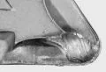
A hollow on the rake face a little back from the edge — where the chip slides. Visible only from above, at an angle.
Chip evacuation and part surface both get worse. When the crater reaches the edge, the edge thins out and breaks without warning.
Cutting speed too high: the temperature where the chip contacts the rake face.
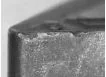
Small breakouts along the edge, a ragged line instead of a straight one.
Cutting forces rise and surface finish suffers.
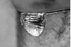
Not small breakouts but a large fracture or a crack across the edge. It happens suddenly.
Tool life becomes unpredictable: one insert lasts the full run, the next one fails on the first part.
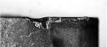
The edge becomes serrated, with small teeth along it.
A burr forms on the part and cutting forces rise.
Feed and cutting speed both too high at the same time.

The nose is neither fractured nor worn but has “flowed” — sagged and spread. Often together with cracks on the nose itself.
Part size drifts, and after that the edge fails catastrophically.
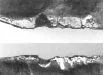
A row of parallel cracks across the edge, like a comb, at roughly equal spacing.
Fragments break out between the cracks and the edge crumbles away.
Temperature swings rather than temperature as such: interrupted cuts, milling, intermittent coolant supply. Excessive Vc and f make it worse.

Cracks appear on an edge that is already heavily worn — as a continuation of the wear band, not on their own.
The machined surface deteriorates sharply and the part size jumps.
Cutting speed too high, plus running the insert beyond its tool life.

Workpiece material stuck to the edge; where the built-up edge tore away, pulled-out patches are left behind.
The surface suffers, cutting forces rise and the size jumps from part to part.
Cutting speed too low on a material prone to adhesion.
The coating comes away in patches, exposing the substrate; the edge looks blotchy.
The exposed substrate wears much faster, and edge failure follows.
| Type of damage | What it leads to | Causes | Actions |
|---|---|---|---|
| Flank wear at the nose | Surface finish, dimensional accuracy | Vc too high; tool life used up | Reduce Vc; grade with higher wear resistance |
| Notching | Burr on the part, rising cutting forces | f and Vc too high | Sharper edge; reduce Vc; grade with better heat resistance |
| Crater wear | Poorer chip evacuation, poorer surface | Vc too high | Reduce Vc; grade for high-speed machining (cermet, coated Al₂O₃) |
| Plastic deformation | Change in part size, cracks on the nose | Very high load; wrong grade | Stronger grade; reduce f and ap |
| Cracking caused by wear | Sharp deterioration of surface, jump in size | Vc too high | Shorten tool life on roughing passes; grade with higher wear resistance |
| Chipping | Rising cutting forces, poorer finish | f too high; vibration; non-rigid setup | Reduce f and ap; more rigid toolholder; stronger grade |
| Cracking from built-up edge | Poorer surface, rising cutting forces | Vc too low | Increase Vc; more precise edge geometry (rake angle, chamfer) |
| Mechanical fracture | Cracks, unpredictable tool life | f and ap too high; vibration | Stronger grade; increase chamfer and rε; more rigid toolholder |
| Thermal cracks, thermal shock | A comb of cracks, chipping between them | Vc and f too high; interrupted cuts and milling | Reduce f and Vc; move to cutting dry |
| Coating flaking | Sharply accelerated wear of the exposed substrate | Insert not strong enough; toolholder not rigid enough | Stronger grade (TiC on CBN); more rigid toolholder; different edge preparation |
One look at the edge replaces three trial batches with different grades. The insert has already written down what happened to it.
When wear is normal it can be measured and tied to a part count. An emergency change becomes a planned one.
Most “unusable” inserts actually work — just not in those conditions. A correct diagnosis keeps them in the programme.