Turning toolholders · external and internal
One and the same grade in one and the same insert behaves differently depending on what holds that insert against its pocket. The rigidity of the assembly, access to the contour, behaviour in an interrupted cut, how fast an edge is changed — all of that is set by the toolholder, not by the insert.
We reply within the working day. There is no minimum order.
The main decision
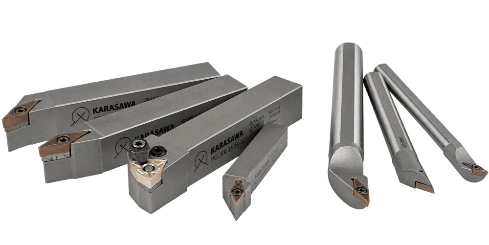
Choosing a toolholder does not start with the shank size. First you settle the insert type: without clearance angles (negative, double-sided — twice as many edges) or with clearance angles (positive, cuts more easily). And each insert type has its own clamping system. Below are all four, as they are described in the KARASAWA programme.
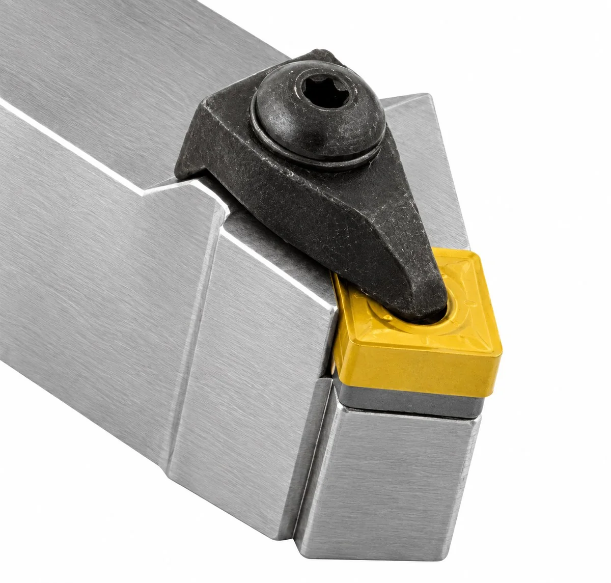
T High-rigidity top clampAn insert without clearance angles is clamped from above by a heavy clamp. The most rigid assembly in the programme.
P Lever clampingThe insert is pulled down by a lever from inside the hole. A universal toolholder with the fastest edge change.
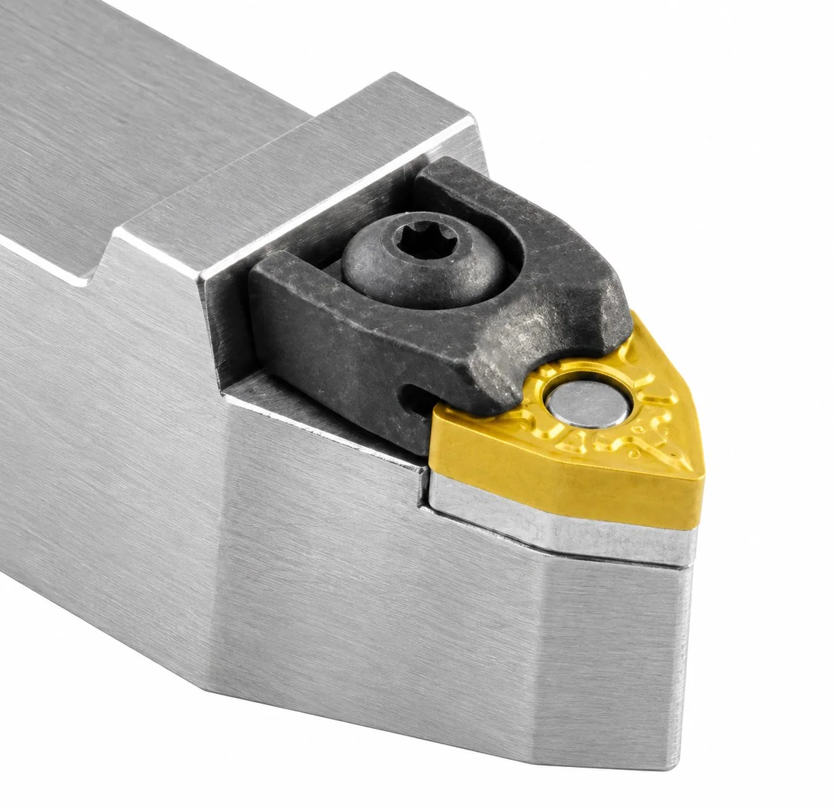
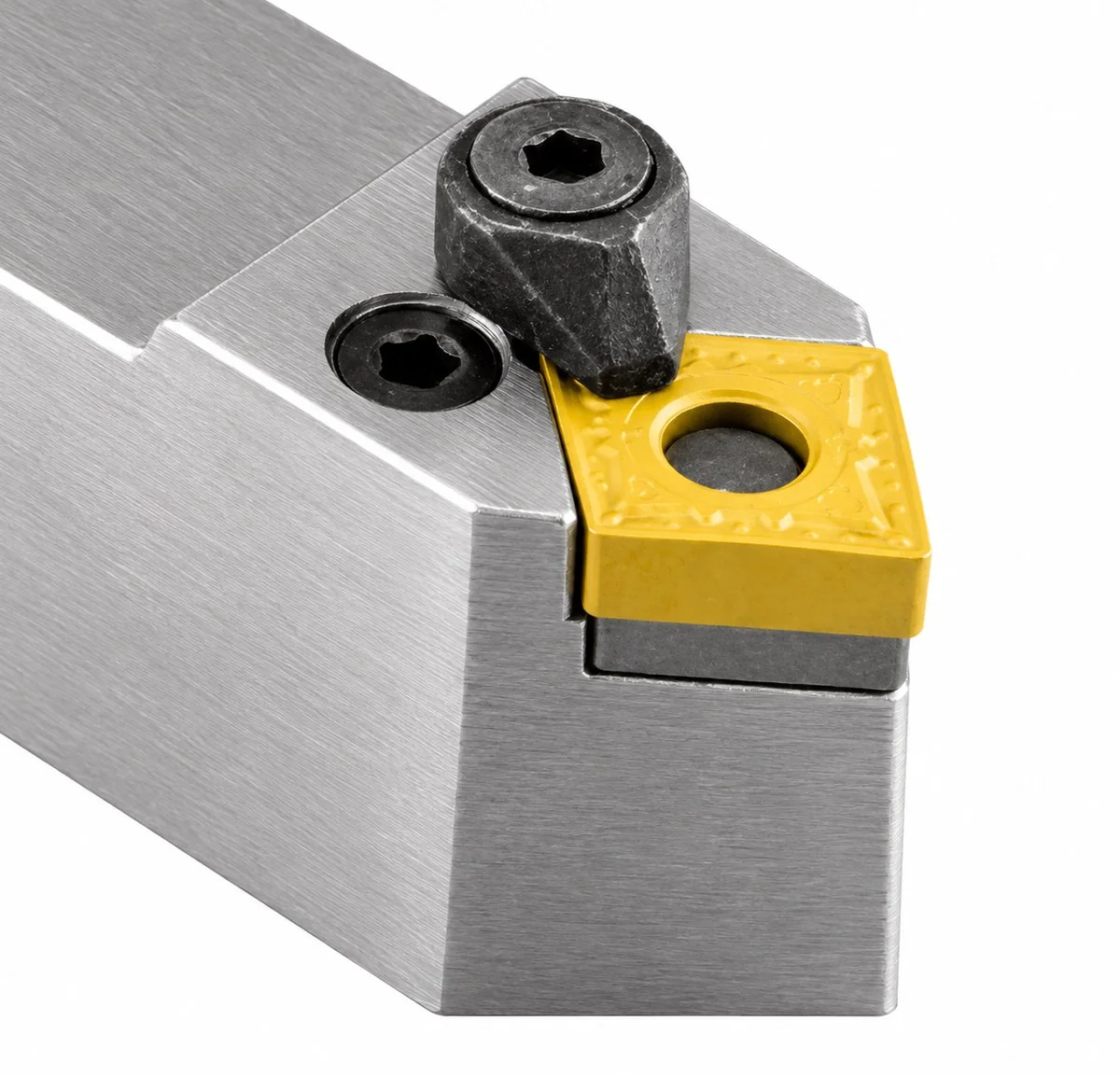
M Wedge clampA combination: clamped from above plus held through the hole by a pin. Its speciality is triangles and trigons.
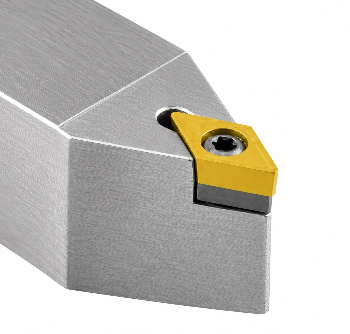
S Screw clampingAn insert with 5° or 7° clearance angles is drawn down by a Torx screw through the central hole. The fewest parts in the assembly.
The assembly
The four clamping systems differ not in “specifications” but literally in the number of parts between the insert and the shank. Every part is both an extra fixing point and an extra second at each edge change. Here is what each assembly is built from.
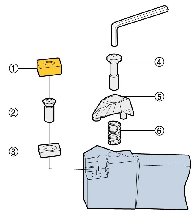
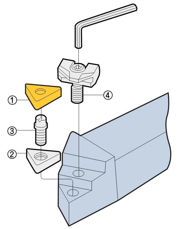
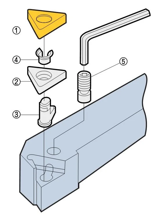
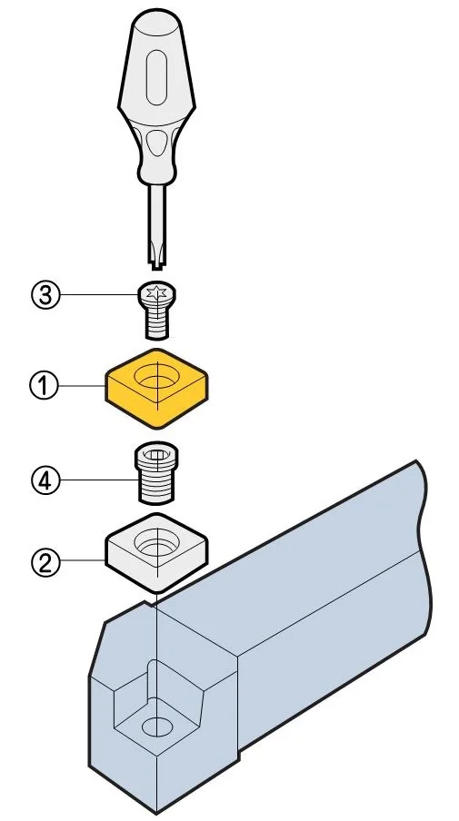
What follows from that. The six parts of the T type mean six contact surfaces which together give the most rigid clamping: which is exactly why this assembly is used for impact and scale. The four parts of the S type mean an empty top face: there is nothing above the insert to obstruct the chip or foul the hole wall. The P type hides the whole mechanism inside the body and gets that same clear top face with a negative insert. The M type adds a pin to the clamp, because the side component of the cutting force tries to rotate a triangular insert in its pocket.
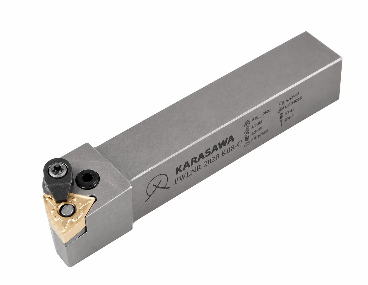
Section 1 · external machining
The simplest case as far as rigidity goes: the tool bears on the tool block over the full height of the shank, the overhang is minimal, and vibration comes only from the part. So the choice here is dictated not by the rigidity of the holder but by access to the contour — where the head of the tool can physically reach without fouling a shoulder or the tailstock.
The second factor is whether the part will take it. A short, solid workpiece allows negative inserts and any clamping. A long, non-rigid one calls for positive inserts with screw clamping: lower cutting forces mean less deflection.
| Job | THigh-rigidity top clamp | PLever clamping | MWedge clamp | SScrew clamping | What it means in practice |
|---|---|---|---|---|---|
| Choosing by the contour being machined · a short, solid workpiece (T, P, M) or a long, non-rigid one (S) | |||||
| Longitudinal turning / facing | ● | ● | ○ | ● | The base operation — any system works. The wedge clamp is limited by insert shape. |
| Contour turning | ● | ● | ● | ● | The only row where all four are suitable. After that it is decided by insert shape and lead angle. |
| Facing | ● | ● | ○ | ● | The same considerations as for longitudinal turning. |
| Machining a necka narrow area between shoulders | ● | ○ | ○ | ○ | Rigid clamping wins here: the tool works in a confined space with no support from the neighbouring surfaces. |
| Interrupted cuttingsplines, slot, flat, eccentric | ● | ○ | ○ | ● | Impact on entry shifts the insert in its pocket. Two assemblies hold it — the heavy clamp and the screw that pulls the insert squarely into its seat. |
| Choosing by the material being machined | |||||
| P Steel | ● | ● | ● | ● | Steel takes anything — the choice follows the rigidity of the part and the stock. |
| M Stainless steel | ○ | ● | ● | ● | A stringy chip does not like a clamp above the insert: it catches on it. The lever and the screw leave the top clear. |
| K Cast iron | ● | ○ | ○ | ● | Cast iron nearly always comes with scale and an interrupted entry — hence the advantage of rigid clamping. |
| N Non-ferrous metals | – | ○ | – | ● | Aluminium and brass are cut with a sharp positive insert — which means screw clamping and nothing else. |
| S Heat-resistant alloys | ● | ● | ○ | ● | Nickel and titanium alloys heat the edge — what matters is full-face support under the insert, not the type of clamp. |
| H High-hardness materials | ● | ○ | ○ | ○ | Hardened steel and hard facing: cutting forces are high, and any give in the assembly comes out as a chipped edge. |
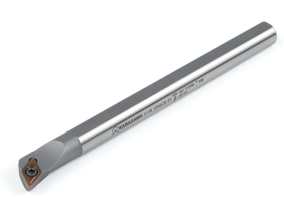
Section 2 · internal machining
Inside a hole all the starting conditions change. The bar is held as a cantilever, and every extra diameter of overhang multiplies deflection by a cube. A second problem appears that does not exist outside: the chip has nowhere to go — it stays in the hole until the coolant washes it out.
So the criteria carry different weight in this table. The clamp that gives the best rigidity outside fouls the wall inside and blocks the approach to the bottom. The screw, which outside is just “one of the options”, becomes the first choice inside for small diameters. And internal coolant supply stops being optional.
| Job | TTop clamping | MWedge clamp | PLever clamping | SScrew clamping | What the hole changes |
|---|---|---|---|---|---|
| Choosing by the contour being machined | |||||
| Longitudinal turning / facing | ● | ● | ● | ● | Through boring is the simplest case; every version is suitable. |
| Profile turning | ● | ● | ● | ● | Decided by insert shape and lead angle, not by the clamping system. |
| Facing inside a holebottom, shoulder, step | ○ | ○ | ● | ● | A clamp above the insert fouls the hole wall. The lever and the screw have nothing on top — the bar reaches closer to the bottom. |
| Interrupted cutting | ● | ● | ○ | ● | Inside a hole the impact is amplified by the overhang of the bar. The lever gives way to rigid clamping here. |
| Choosing by the material being machined | |||||
| P Steel | ● | ● | ● | ● | Universal. After that look at the overhang: beyond 4×D, a carbide shank. |
| M Stainless steel | ○ | ○ | ● | ● | A long stringy chip in the hole is the main problem. Assemblies with a clear top and internal coolant win. |
| K Cast iron | ● | ● | ○ | ● | The chip is short and evacuation is no problem — rigidity comes to the fore. |
| N Non-ferrous metals | – | – | ○ | – | A special case: sharp positive inserts and plenty of space for the chip are needed. |
| S Heat-resistant alloys | ● | ● | ● | ● | What becomes critical is coolant delivered under pressure into the cutting zone, not the method of clamping. |
| H High-hardness materials | ● | ● | ○ | ○ | Hard material inside a hole is the toughest scenario: rigid clamping plus a carbide bar. |
The short rule. Cast iron, scale, interrupted cutting — the high-rigidity top clamp (T). General turning of steel in large batches with fast edge changes — the lever (P). Triangles and profiles — the wedge clamp (M). Thin walls, non-rigid parts, non-ferrous metals, a small hole at a long overhang — the screw (S).
In summary
The insert is a consumable: it is changed every shift. The toolholder stays in the shop for years and determines how calmly those changes go. So what matters in it is not “specifications” but three things that only show in use.
A shim under every pocket, Torx screws, reinforced clamps. The hundredth insert seats where the first one did — the size does not drift after an edge change and the operator does not have to find zero again.
Designations to ISO 5608 mean a toolholder can be ordered from a drawing rather than from one particular brand's catalogue. The insert, screw and key designations are engraved on the body — a reorder takes a minute rather than half a day.
Rigid clamping for cast iron and scale, the lever for production steel, the wedge clamp for profiles, the screw for thin walls and small holes. You do not have to cover the whole shop with one type and then explain where the chipped edge came from.