Tooling for Swiss-type lathes
On a sliding headstock lathe the tool block is packed tight: you physically cannot get a key to the insert screw inside the working area, and removing the holder takes the tool offset with it. A quick-change system separates those two things: the base stays clamped in the block along with all its coordinates, while the cutting head with its insert comes off with one hand.
We reply within the working day. There is no minimum order.
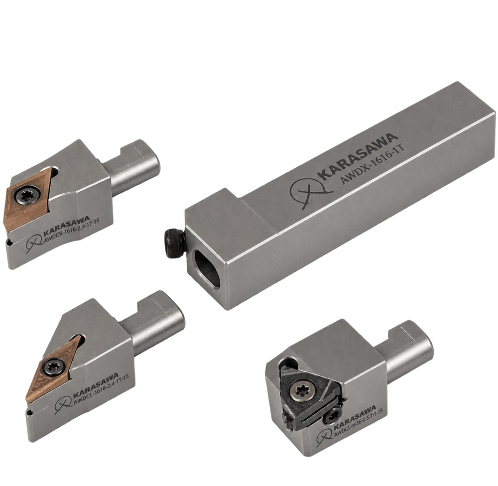
General description
A sliding headstock lathe lives on small batches: 200–500 parts, then a changeover. In that regime the losses come not from cutting but from the standstills between cuts — and the biggest of them is the one everyone has got used to: changing an insert inside a cramped tool block.
A quick-change system splits the toolholder into two parts with different lifespans. The base stays in the block permanently. The head is the consumable part of the tooling, removed, swapped and replaced as a whole.
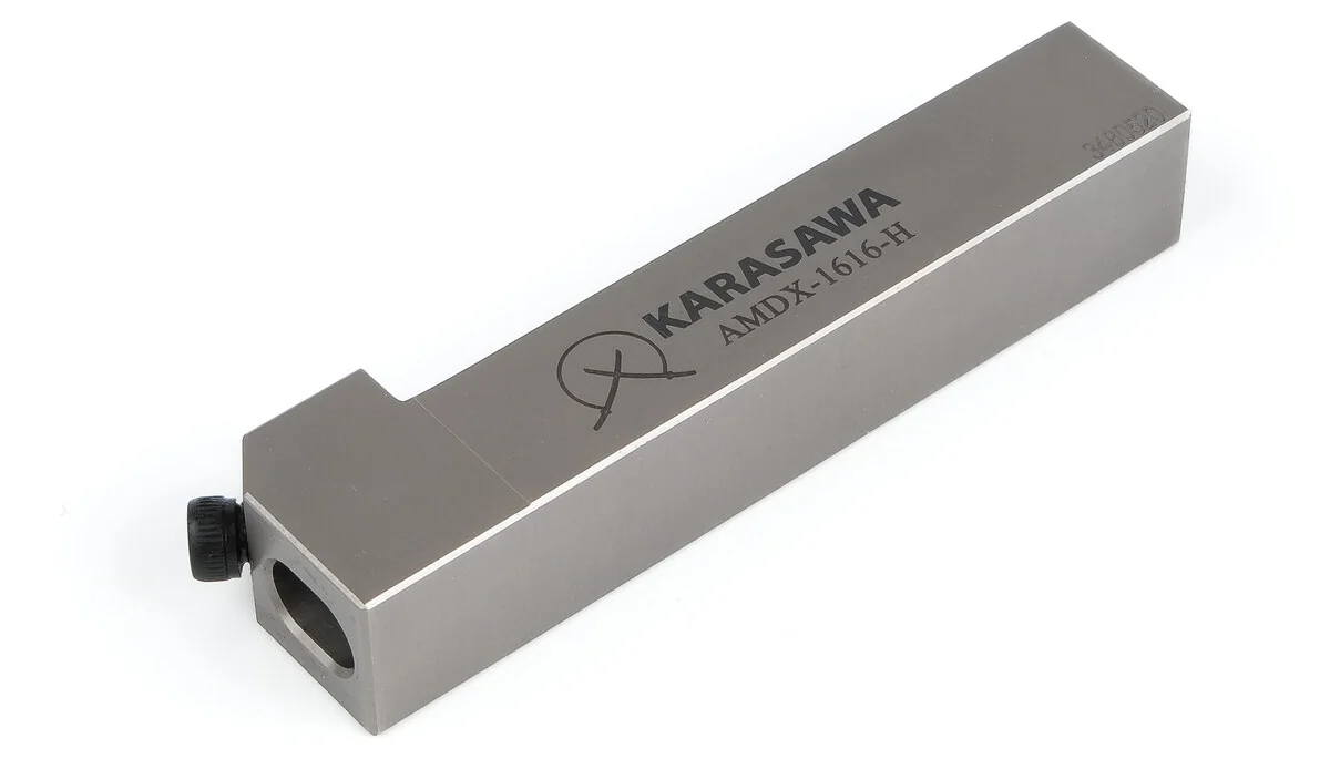
The base
A 12×12 or 16×16 mm square shank is clamped in the machine's tool post exactly like an ordinary turning tool. On the front face there is a precise pocket for the head shank with a flat, and a single side locking screw: it both clamps the head and sets its angular position.
A coolant channel runs through the body of the base. The fluid is delivered under pressure not from a nozzle at the side that has to be aimed every time but from inside the tool — straight into the zone where the chip meets the rake face. The index H at the end of the designation means exactly this version.
The base takes no part in cutting and does not wear. Its coordinates in the part program are set once, when the machine is set up.
The head is removed whole and taken to the bench. The insert screw is undone in decent light rather than blind between the slideways — and it does not drop into a tray full of chips and oil.
Since nothing was taken out of the block, the tool overhang has not changed. Once the head is back on, the cycle continues with the same offsets — the changeover comes down to a single operation.
Heads for different purposes fit the same base. A position in the block that used to be occupied by one tool for good can now do turning, and threading on the next part.
Tools by application
The heads differ not in “class” but in the shape of insert they hold. The shape sets two things at once: how strong the tool nose is and what contour that nose can physically reach into. Everything else — section, version, size — is chosen after that.
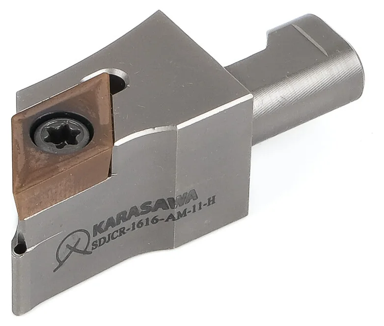
The workhorse of a Swiss-type lathe. A 55° nose angle is a compromise that carries the whole part: longitudinal turning, facing and a short angled back-cut with one edge.
DC_T 0702 or DC_T 11T3, 7° clearance angle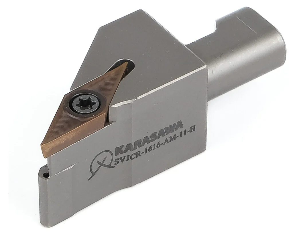
A sharp rhombic reaches where the 55° fouls with its shoulder: tapers, fillets, angled grooves, undercutting beneath a shoulder. The price of sharpness is a thinner nose, so the cutting data is lower.
VC_T 1103, 7° clearance angle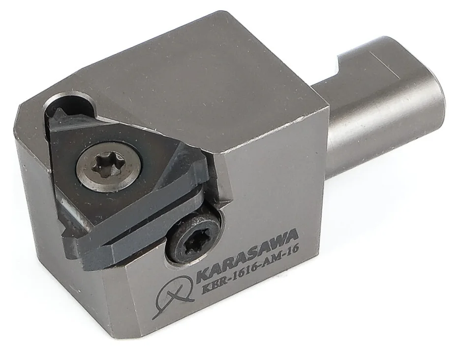
The threading insert is held not by a screw through a hole but by a clamp from above: a threading insert has no central hole, and the profile has to bear on solid support.
11ER / 11EL or 16ER / 16ELHow the code reads
Why this is on the site. The first four letters are ISO 5608, the same standard as on ordinary turning tools. An engineer does not have to learn a proprietary system: he reads the code the way he has read it all his life. And the full designation is engraved on the body of every head — a reorder is made with the tool in your hand, without a catalogue.
Choosing a set
A set for a Swiss-type lathe is assembled in three steps, each of which narrows the choice. The part contour decides which rhombic — 55° or 35°. The material decides the grade. The cutting data and the surface requirement decide the chipbreaker. Below, that same sequence is condensed into one line for each typical job on a sliding headstock lathe.
| The job on the machine | Head | Insert | Chipbreaker | KARASAWA grade | Why this one |
|---|---|---|---|---|---|
| Steel — shafts, fittings, fasteners, studs | |||||
| Longitudinal turning, generalthe main stock removal on the machine | SDJC…AM-11 |
DCMT 11T3 |
MP |
K1775 |
Cermet does not stick to steel: the chip slides away and the surface comes out mirror-like with no separate finishing pass. There is one condition — cutting without impact, and on bar work there is none. |
| Finishing pass to sizeinstead of grinding | SDJC…AM-07 |
DCGT 0702 |
F · SQ |
K1775 · PM1775 |
The sharpest geometry in the line in a small size. A smaller insert means a smaller nose radius, which means hitting the size more precisely at small stock. |
| Small part, thin wallsa long bar overhang out of the collet | SDJC…AM-07 |
DCGT 0702 |
J · W · U |
PM1775 · MS1385 |
The J chipbreaker was made specifically for small parts on Swiss-type machines. An ultra-fine 0.3–0.4 µm grain holds hardness and toughness at the same time — the edge neither chips nor drifts through the batch. |
| Stainless and heat-resistant alloys — medical, fittings, instruments | |||||
| Stainless, finishingimplants, fittings, sensor housings | SVJC…AM-11 |
VCMT 1103 |
MC · MK |
MP2575 |
A dedicated stainless item: a fine grain gives a strong edge and a heat-resistant coating takes flood coolant. In stainless the edge dies not from wear but from built-up edge — that is the point here. |
| Stainless, low cutting forcesthin-walled part | SVJC…AM-11 |
VCGT 1103 |
FM · FL |
MS1385 |
A lightened geometry plus a black PVD coating on an ultra-fine grain. FL is the FM variant for even lower forces: for when the part deflects before the insert wears. |
| Titanium and nickel alloysheat-resistant group S | SVJC…AM-11 |
VCGT 1103 |
FP · FS |
PS1255 |
A thin AlTiSiN layer does not blunt the edge, and the silicon in it resists oxidation at high cutting temperatures. This is the same pairing that works on titanium implants. |
| Non-ferrous metals — electronics, fittings, pneumatics | |||||
| Brass, bronze, copper, aluminiummain series | SDJC · SVJC |
DCGT · VCGT |
AX |
NN1070 |
A polished uncoated edge. Any coating rounds the edge by a few microns — with soft non-ferrous metals that is enough to turn cutting into crushing and a built-up edge. |
| High-silicon aluminiumabrasive aluminium alloy | SDJC · SVJC |
DCGT · VCGT |
AX4 |
NN1050 |
Silicon wears ordinary carbide away like chalk. A diamond-like layer pushes that limit back by an order of magnitude — in the same shift you change one insert instead of ten. |
| Special cases | |||||
| Ultra-sharp edge, precise contour“E” series, right- and left-hand | SDJC · SVJC |
DCET · VCET |
X · Y |
PS1255 · PS2255 |
The “E” inserts are as sharp as carbide can be made. Y is the same class with a reinforced edge, for when the ultra-sharp one is starting to chip. |
| Hardened steel at light cutting dataHRC 45 and above | SVJC…AM-11 |
VCGT 1103 |
FS |
PS1255 |
The widest finishing geometry by insert shape. On a Swiss-type machine a hardened part is run at small stock — exactly the regime in which a wear-resistant PVD grade works instead of CBN. |
| External threadingthe same station in the block | KER · KEL |
11ER · 16ER |
— | by thread profile | A threading insert has no chipbreaker in the usual sense — its “geometry” is set by the profile and the pitch. Grades and profiles are set out on the threading inserts page. |
How to use this. A row of the table is a ready-made set: the base for your block section, the head, the insert, the chipbreaker and the grade. If a part combines several rows — and on a Swiss-type machine it nearly always does — you take one base and several heads: that is cheaper than several complete toolholders and faster than swapping inserts in one.
Inserts
The heads in this system hold inserts in two ISO shapes — 55° rhombic (DC..) and 35° rhombic (VC..), both positive, with a 7° clearance angle, in sizes 0702, 11T3 and 1103. That is a narrow slice of the range — and within it the KARASAWA programme holds sixteen different chipbreakers.
A chipbreaker is not an “optional extra” on an insert but precisely what makes one insert different from another of the same shape. The crater on the rake face determines the angle at which the chip comes away, how much force that takes and where it breaks. On a Swiss-type machine that is critical: a chip wrapped around the part here does not spoil the surface — it stops the automatic cycle.
| Chipbreaker | Zone | Shapes for these heads | Grades | Purpose |
|---|---|---|---|---|
| Finishing — the main zone on a Swiss-type machine | ||||
| F | Finishing | DCGT |
K1775PM1775MS1385 |
The sharpest finishing geometry in the line. Small parts, small stock, a surface finish requirement. |
| FM | Finishing | DCGTVCGT |
PM1775MS1385 |
A universal finishing geometry on an ultra-fine-grain substrate. It holds size right through the batch — the very thing the machine was bought for. |
| FL | Finishing | VCGT |
PM1775MS1385 |
A lightened version of FM for even lower cutting forces: thin walls and non-rigid parts at a long overhang. |
| FP | Finishing | VCGT |
PS1255 |
Finishing on a 35° rhombic with a wear-resistant PVD grade: heat-resistant alloys and titanium. |
| FS | Finishing | VCGT |
PS1255 |
The working geometry for hardened steel and nickel alloys at light cutting data. |
| J | Finishing | DCGT |
PM1775MS1385 |
A special 55° rhombic crater for small parts on Swiss-type machines. Right-hand version only. |
| U | Finishing | DCGT |
K1775PM1775MS1385NN1070 |
A universal finishing geometry available at once in cermet, two PVD grades and an uncoated grade — one geometry for steel, stainless and non-ferrous metals. |
| W | Finishing | DCGT |
PM1775MS1385 |
A version of U with a different crater profile for a wider feed range. |
| X | Finishing | DCETVCET |
PS1255 |
The “E” series — an ultra-sharp edge for small precision parts. Right- and left-hand versions. |
| Y | Finishing | DCETVCET |
PS1255PS2255 |
The same class as X, but with a reinforced edge — for when the ultra-sharp one starts to chip. |
| Semi-finishing and medium machining | ||||
| SQ | Semi-finishing | DCMT |
K1775 |
Cermet semi-finishing: finishing passes in steel without grinding. |
| MP | Medium | DCMT |
K1775 |
The widest cermet item in the programme. Medium cutting data, a stable surface — the base choice for steel on a Swiss-type machine. |
| MC | Medium | VCMT |
MP2575 |
A dedicated stainless item: a fine grain plus a heat-resistant coating. |
| MK | Medium | VCMT |
MP2575 |
The same on a 35° rhombic — contours in stainless. |
| Non-ferrous metals | ||||
| AX | Non-ferrous | DCGTVCGT |
NN1070 |
A polished uncoated edge. The main series for brass, bronze, copper and aluminium. |
| AX4 | Non-ferrous | DCGTVCGT |
NN1050 |
The same geometry in a grade with a diamond-like layer — against the abrasive silicon in high-silicon aluminium. |
Why there are no roughing geometries in this list. A sliding headstock lathe works small-diameter bar supported by a guide bush a few millimetres from the tool. The depth of cut here is measured in tenths, not millimetres, and a heavy roughing geometry on such a part simply never gets going: its crater is designed for a thick chip that will not be there. So this class concentrates on the finishing and medium zone — and that is exactly where the range is widest.
Grades
A grade designation can be read without a reference book. The first letters are the ISO 513 groups it was created for: PM — steel and stainless, PS — steel and heat-resistant alloys, MS — stainless and heat-resistant alloys, MP — stainless, NN — non-ferrous metals, K — cermet. Then come the application figures and the coating technology code.
The mark in a cell says not “suitable or not” but what kind of cutting the grade will take in that material.
| Grade | Technology | PSteel | MStainless | KCast iron | NNon-fer. | SHeat-res. | HHardened | Where it works on a Swiss-type machine |
|---|---|---|---|---|---|---|---|---|
| Cermet with a PVD coating | ||||||||
| K177592,5–93,5 HRA | Cermet + PVD | ● | – | – | – | – | – | A steel part with a mirror surface and no separate finishing operation. Cermet does not forgive impact — but on bar work there is none, so a Swiss-type machine is the ideal environment for it. Geometries MP, SQ, F, U. |
| Carbide with a PVD coating | ||||||||
| PM177593,5–94 HRA | PVD on an ultra-fine 0.3–0.4 µm grain | ● | ● | – | – | – | – | Finishing in steel and stainless. The ultra-fine grain gives the rare combination of 94 HRA hardness with impact toughness: the edge holds both the size and the occasional knock against a blank. The coating has a violet tint. |
| MS138593,5–94 HRA | PVD on an ultra-fine 0.3–0.4 µm grain | ● | ● | – | – | ● | – | The same substrate, a different coating — black. Stainless and heat-resistant alloys, including thin-walled parts where low cutting forces matter. |
| PS1255wear-resistant | PVD · AlTiSiN | ● | ○ | ● | – | ● | ○ | Titanium, nickel alloys, hardened steel at light cutting data. The thin layer does not blunt the edge. Corrosion-resistant: the insert does not bloom in the emulsion or in the store. |
| PS2255universal PVD | PVD · AlTiSiN | ● | ● | ● | – | ● | – | Four ISO groups out of one box. For a shop that changes material to order every week, that means fewer items on the shelf. It will take light interrupted cutting. |
| MP2575fine grain | PVD on a fine-grain substrate | – | ● | – | – | – | – | A narrow speciality — various stainless steels at medium and low speeds, when a strong edge and a high surface quality are needed at the same time. The coating colour is a dark blue-grey. |
| Carbide uncoated and with a diamond-like layer | ||||||||
| NN1070submicron grain | Uncoated, polished edge | – | – | – | ● | – | – | Brass, bronze, copper, aluminium — that is, a good half of everything turned on these machines at all. A submicron grain allows the edge to be ground sharper than any coating permits. |
| NN1050diamond-like layer | CVD · Diamond-like | – | – | – | ● | – | – | Aluminium alloys with a high silicon content that eat ordinary carbide within a dozen parts. AX4 geometry. |
The KARASAWA programme has sixteen turning grades, CVD, PCD and CBN included. This page shows eight — exactly those in which inserts of the DC.. and VC.. shapes are produced in the required sizes. The rest live in larger inserts for conventional lathes and are set out on the turning inserts page.
Coating
A coating a few microns thick gives a bigger gain in tool life than any change of substrate composition. But there is no single “good” coating: what saves the edge in cast iron at high speed will come off in stainless within a minute, and in brass it only gets in the way. That is why the KARASAWA programme has not one coating but nine different technologies — and that is exactly where the breadth of the range comes from.
The difference between CVD and PVD is not marketing but physics. CVD is deposited at 900–1000 °C: the layer comes out thick, multilayer, with an interlayer of aluminium oxide acting as a thermal barrier. Such a layer takes high speeds, but the edge under it is slightly rounded — by a few microns. PVD is applied at 400–500 °C: the layer is thin, the edge stays sharp, and it carries compressive stresses that hold the edge against chipping.
And this is exactly why there is no thick CVD in this section at all. A few microns of edge rounding is nothing on a Ø80 shaft and half the stock on a Ø4 part. On a sliding headstock lathe edge sharpness is not a “desirable property” but the condition of the part coming out to size at all. So what works here is six technologies out of nine: cermet, four different PVD coatings, a diamond-like layer — and the complete absence of a coating as a separate and entirely deliberate technology.
| Technology | Colour | Grades | What it does in the cut on a Swiss-type machine |
|---|---|---|---|
| PVD on an ultra-fine grain0.3–0.4 µm, 93.5–94 HRA | violet, black | PM1775MS1385 |
What works here is not so much the layer as what is under it. A grain several times finer than usual gives 94 HRA hardness and high transverse rupture strength at the same time. For a production run that means one thing directly: the size does not drift from the first part to the last. |
| PVD AlTiSiNwear-resistant, corrosion-resistant | grey steel | PS1255PS2255 |
The silicon in it forms a dense, oxidation-resistant film on the surface. The thin layer does not eat into sharpness — hence titanium, nickel alloys and thin walls. Corrosion resistance matters outside the cut too: the insert does not deteriorate in a wet emulsion or in an open box on the machine. |
| PVD on a fine grainheat-resistant | dark blue-grey | MP2575 |
High resistance to thermal shock. On these machines the fluid is delivered under pressure straight into the cutting zone through the tool — so the edge is constantly going through a heat-then-quench cycle. This coating was made for exactly that. |
| PVD on cermetTiC–TiN substrate | light grey | K1775 |
Cermet has a lower affinity for steel than tungsten-cobalt carbide: the chip does not stick and the surface comes out mirror-like. The coating adds wear resistance without taking that property away. The price is low toughness: cermet does not forgive impact, and on a Swiss-type machine that is not a problem. |
| Diamond-like CVDdiamond-like, thin layer | dark grey | NN1050 |
The only CVD coating in this class — and precisely because it is thin and does not round the edge. Against the abrasive silicon in high-silicon aluminium: ordinary carbide there wears away like chalk. |
| Uncoatedsubmicron grain, polished edge | polished carbide | NN1070 |
Sometimes the best coating is no coating. Any layer rounds the edge by a few microns; with brass, copper and aluminium that is enough to turn cutting into crushing and a built-up edge. A polished uncoated edge cuts cleanly. |
Coating colour is a working tool for the operator, not decoration. It tells the grade apart in an unlabelled box and shows how worn the edge is: a worn-through layer is visible to the naked eye before any instrument shows the size going out. On a machine where inserts are changed to a schedule rather than when scrap appears, that is worth real money.
In summary
A sliding headstock lathe is bought so that the part comes out finished in one setup. Anything that stops that cycle costs more than an insert — and that is exactly what a quick-change system is designed for.
The base never leaves the block, so the overhang and the offsets stay where they are. The head comes off and goes back on with one screw — an operation for the operator rather than the setter, and one done between batches rather than at the end of a shift.
A 55° rhombic for longitudinal turning, a 35° rhombic for contours, a threading head — all on one body clamped in the block. A station in the block stops being tied to one operation for good.
The full designation is stamped on the body of every head. Six months later, when the inserts run out, the reorder is made with the tool in your hand — and exactly what was there before arrives. That is what predictability means in practice.