Carbide reamers
A reamer does not make the hole — it brings it to size. The drill gave you Ø9.8 with a tolerance in tenths; the reamer turns that into an H7 fit with a mirror wall. And it does it in one pass, in seconds, with no boring and no grinding.
We reply within the working day. There is no minimum order.
The main decision
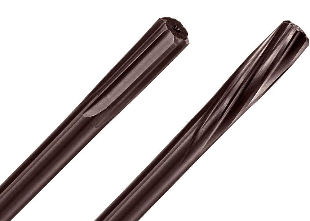
Choosing a reamer starts not with the diameter or the coating but with one question: where will the chip go. A reamer removes stock in hundredths of a millimetre — the chip comes off thin, long and stringy. If it goes the wrong way, it will travel down the wall the tool has just brought to size and leave a groove. The hole will be within tolerance on diameter and scrap on surface finish.
So the flute is chosen by the type of hole, not out of habit. A through hole and a blind hole are two different chip evacuation problems, and one tool will not solve both properly.
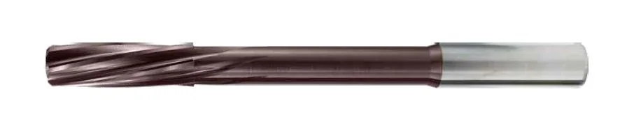
Where the chip goes. A left-hand helix with right-hand rotation works like an auger pointing forwards: the chip is pushed out ahead of the tool and falls out of the far side of the part. It never comes back along the machined surface at all.
The second effect is smoothness. A helical edge enters the material gradually rather than along its whole length at once. That removes the impact on entry, damps vibration and saves the day where a hole crosses a slot, a groove or another hole: a straight edge “snaps” at such a crossing, a helical one passes through evenly.
The limitation. Through holes only. In a blind hole the chip has nowhere to go: it packs into the bottom, the tool jams and breaks — often taking the part with it.
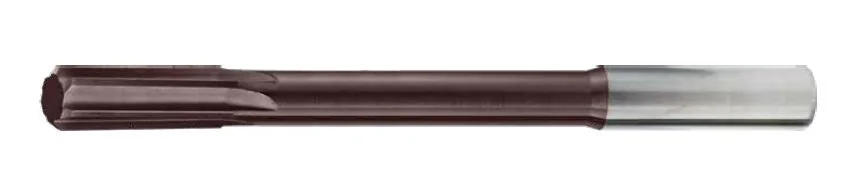
Where the chip goes. A straight flute does not drive the chip anywhere by itself — it simply gives it a channel. The direction is set by the coolant: with internal supply the emulsion hits the bottom of the hole and washes the chip up along the flutes. That is exactly why a blind hole is reamed with a straight flute and internal cooling, not with a helical one.
The second effect is rigidity. Straight flutes leave more metal in the core than helical ones of the same depth. The tool twists less under load and holds the axis more accurately — at small diameters and long overhangs that is noticeable.
The limitation. On entry the edge meets the material along its whole length at once — the impact is greater than with a helical flute. On an interrupted surface a straight flute behaves worse.
| Criterion | Helical flute | Straight flute |
|---|---|---|
| Through hole | The main choice — the chip goes forward, out of the part | Works if the chip is short or there is internal coolant |
| Blind hole | Do not use | The only correct option, preferably with internal coolant |
| Interrupted wallslot, hole, groove | Smooth entry of the edge, no impact | The edge “snaps” at every crossing |
| Ductile materialstainless, low-carbon steel | The long chip is led forward in a controlled way | Risk of the chip wrapping around the flute |
| Brittle materialcast iron, bronze, brass | Excessive — the chip breaks up anyway | Optimal and cheaper |
| Tool rigidity | Lower, all else being equal | Higher — a thicker core |
| Wall finish | Consistently high — the chip does not come back | High, provided the chip is evacuated properly |
The short rule. Through hole — helical. Blind hole — straight with internal coolant. Brittle material and a simple hole — straight, it is cheaper and more rigid. Everything else is a matter of cutting data.
Model range
Three versions cover practically the whole range of precision holes in a machine shop.
Left-hand helix, external coolant supply. The main application is through holes to a fit: bearing seats, holes for dowels and guide bushes, precision holes in housing parts.
The diameter steps run in microns — Ø2.99 · Ø3.00 · Ø3.01 and so on. You take a reamer for a specific fit rather than adapting the process to the tool size you happen to have.
The universal version: blind and through holes, and the widest diameter range in the line — up to Ø20 mm. A straight flute leaves no helical mark on the wall and holds the axis at a long overhang.
The working choice for cast iron, bronze, brass and short-chipping steel, and for sections where one reamer has to cover several different parts.
The version for blind holes and for anything deeper than 2–3 diameters. The emulsion is fed through the body of the tool straight into the cutting zone and carries the chip up from the bottom — where an external jet physically cannot reach.
This is the case where internal cooling is not a “nice option” but a condition of the job: without it the chip in a blind hole has nowhere to go.
If you need a non-standard diameter, taper or length, we make to size. Availability of a specific item is confirmed in our reply to your enquiry.
Coating
On a drill the coating protects the edge from temperature. On a reamer the task is different: the stock is small and there is comparatively little heat — what becomes critical is friction. The chip travels along the whole length of the flute, pressed against the hole wall, and any roughness in the coating means a risk of adhesion and scoring.
That is why the whole KARASAWA reamer line comes with the polished ECO-X coating: the same TiAlN chemistry as the basic ECO, but with a polished surface — the coefficient of friction is roughly a quarter lower. The chip slides instead of dragging, and ductile material starts sticking to the edge noticeably later.
| Coating | Colour | Composition | Hardness HV0.05 | Working t° | Coeff. of friction | What it gives on a reamer |
|---|---|---|---|---|---|---|
| ECO-Xsmooth, standard | TiAlN | 2800–3100 | 800–900 °C | 0,3–0,4 | The standard for all RH, RS and RSC series. Low friction in the flute, a clean hole wall, a stable size right through the batch. | |
| MEGAnanolayer, on request | AlTiSiN | 3500–3800 | 1100–1200 °C | 0,3–0,4 | For reaming stainless or heat-resistant alloys in large batches: a harder layer keeps the edge in size for longer. Available on request. |
In practice
The most common cause of scrap is not the tool but the wrong stock allowance. Too little and the reamer rubs instead of cutting: the edge strokes the work-hardened layer, heats up and dulls within a dozen holes. Too much and the tool behaves like a drill, the axis wanders and the size drifts.
| Hole diameter | Stock on diameter | Drilling diameter | Comment |
|---|---|---|---|
| up to Ø5 | 0.1–0.15 mm | Ø4.85–4.90 for Ø5 H7 | At small diameters the stock is reduced: the tool is slender and the torque is limited. |
| Ø5–10 | 0.15–0.2 mm | Ø9.8 for Ø10 H7 | The most common case. A DP series drill produces exactly this pre-hole. |
| Ø10–20 | 0.2–0.3 mm | Ø19.7–19.8 for Ø20 H7 | For ductile materials take the upper limit — the edge has to cut, not slide. |
It works the other way round. At too low a feed the edge does not bite but crushes the metal — the surface is worse, the size drifts up and the tool dulls faster. A reamer likes a high feed and a moderate speed.
Reverse drags the chip between the edge and the wall — and leaves a score in a hole that has just been brought to size. Retract in forward rotation only, at working feed.
A reamer follows an existing hole and is entitled to a little self-alignment. Runout above 0.01 mm will be transferred to the hole diameter — to the size and to the taper.
In summary
A precision hole can be produced three ways: boring, grinding or reaming. The first two mean separate tooling, a separate machine and minutes per part. The third means seconds and one tool in the magazine.
H7 and a mirror wall are obtained on the same machine, immediately after drilling. The part does not travel to a boring or grinding machine — so there is no refixturing and no error from it.
Micron diameter steps mean you take the tool for a specific joint. Not “near enough, we will compensate with the cutting data”, but exactly the size the drawing calls for.
Through, blind, with a crossing hole — the programme has a version for every case. You do not have to cover every job with one reamer and then explain to inspection where the score came from.