Grooving and parting
Grooving and parting is the only turning operation where the tool goes into its own cut and has nowhere to send the chip. An insert three millimetres wide carries the whole cutting force, and the toolholder has no reserve of rigidity at all. So what wins here is not a “universal” tool but a precisely matched pair of toolholder and insert.
We reply within the working day. There is no minimum order.
Tools by application
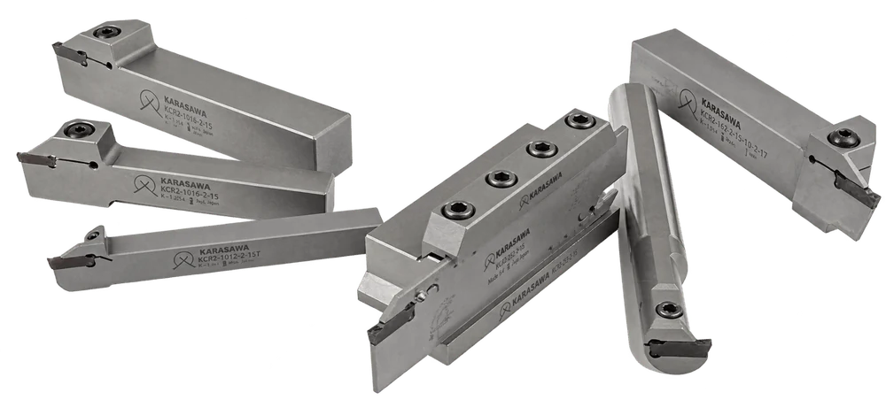
A groove can be external, internal or in the face, and parting off depends on how deep you have to go into the body of the workpiece. Those are four different geometric problems, and each is covered by its own family of toolholders. They have one thing in common: a self-clamping pocket — the insert is held by the springiness of the holder itself, with no clamping screw, for which there is simply no room in a cut three millimetres wide.
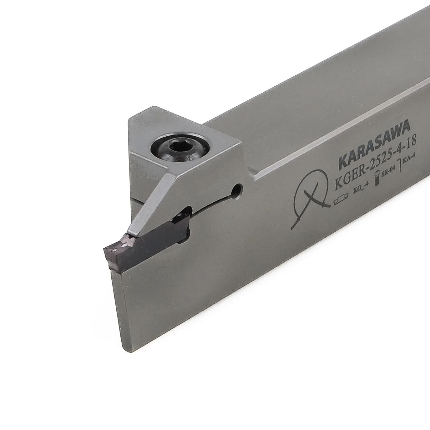
A square shank with the insert set out to the side of the body. The workhorse of the section: cutting a circlip groove, facing a shoulder, parting a finished part off the bar.
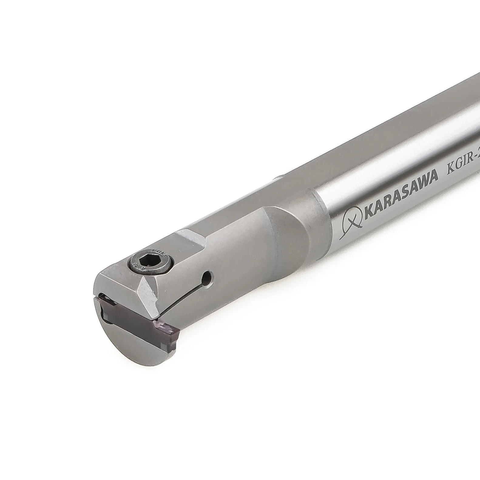
A round bar with a cutting head on the end. Grooves for circlips and seals inside a hole — where an ordinary tool physically cannot be turned round.
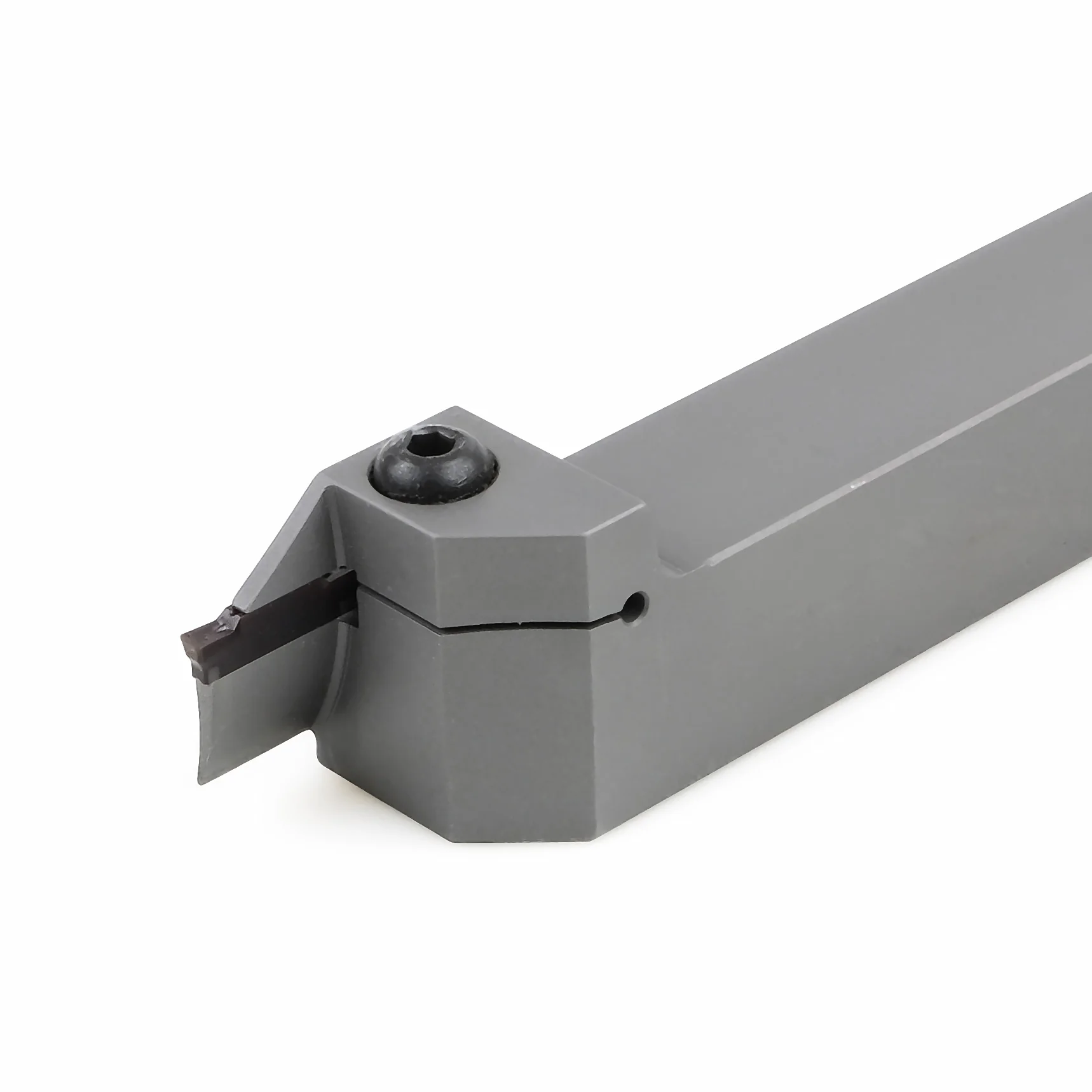
The cutting portion is curved on an arc. The groove cuts into the face of the part — for a seal, a labyrinth, a bearing seat. The curvature of the body is chosen to suit a specific diameter range.
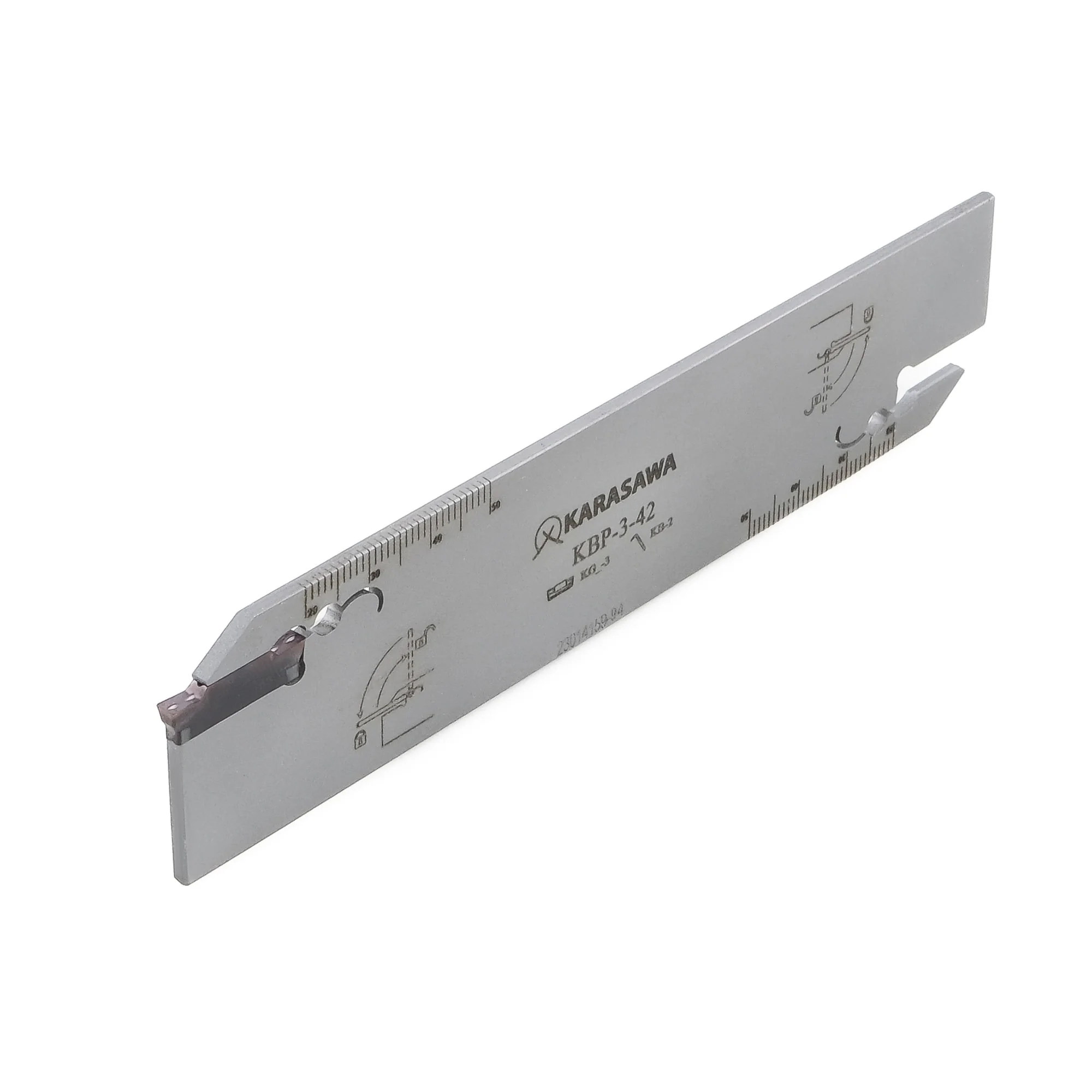
A flat blade with two insert pockets, clamped in a heavy block holder. The classic of bar parting: rigidity where it is needed and a minimal section where it gets in the way.
KBP — the insert width and blade height are in the designationKBH — to suit the tool block size| Toolholder family | What it does on the part | Shank | Cut width | Depth | When you take this one |
|---|---|---|---|---|---|
| External machining | |||||
| KGER / KGELgrooving and parting, right and left | Grooves on a cylindrical surface, facing a shoulder, parting a part off the bar | 12×12 … 32×32 | 1.5–8 mm | 10–32 mm | The universal option for a section. One holder covers both grooving and parting, provided the bar diameter fits within the depth |
| KGE…Rreinforced version | Deep parting with a greater insert overhang | 20×20 · 25×25 | 3–4 mm | up to 28 mm | For when an ordinary body no longer reaches the depth but it is still too early to go to a blade |
| KGE…STSwiss Type | Grooving and parting on sliding headstock lathes | 12×12 · 16×16 | 2–3 mm | 12–16 mm | A small precision part out of a collet: short overhang, low centre height, thin walls |
| KGE…Hcoolant through the tool | Parting and deep grooving with emulsion fed straight into the cut | 20×20 · 25×25 | 3–5 mm | 20–25 mm | Stainless, titanium, heat-resistant alloys and any deep groove where the chip will not come out on its own |
| Internal and face machining | |||||
| KGIR / KGILinternal grooving | A groove for a circlip, a seal or a thread run-out inside a hole | Ø16 … Ø40 | 2–5 mm | 4–12 mm | The minimum hole diameter dictates the bar, not the other way round. Lengths 150–300 mm — to suit how deep the groove lies |
| KGEFR / KGEFLface grooving | An annular groove in the face — for a seal, a labyrinth, a seat | 25×25 · 32×32 | 3–8 mm | 17–45 mm | Must be ordered for a specific diameter range: the body is curved on an arc and on the wrong diameter will foul the groove wall |
| Parting with a blade | |||||
| KBP + KBHblade and block holder | Parting large-diameter bar, production work from a bar feeder | 25 mm block | 2–4 mm | by blade height | For when you have to go deeper than a solid body allows without widening the cut — every extra millimetre is metal turned into chips |
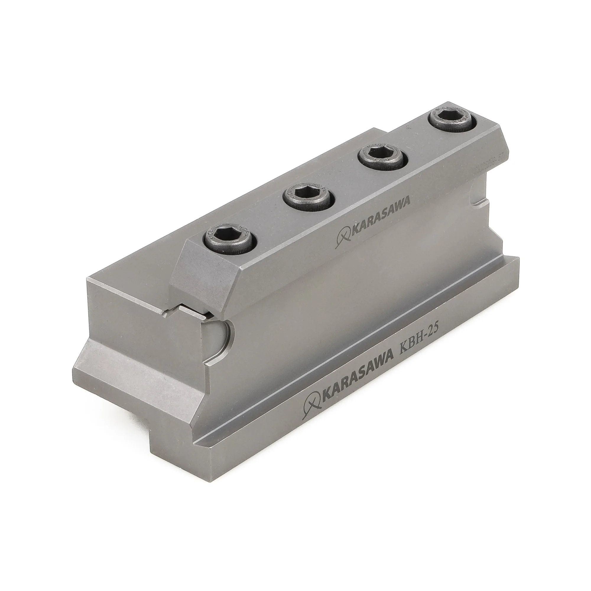
A solid parting toolholder has a natural limit: to go deeper you either have to extend the insert further from the body or make the cut itself wider. Both routes are bad. A blade solves the problem differently — it separates the functions. The heavy KBH block holder takes all the rigidity on itself and mounts in the tool block like an ordinary holder. The slim KBP blade carries only the insert, and its section can be kept minimal because the bending is taken by the block.
In practice that means this. The cut width stays at 2–3 mm even on a large bar diameter — metal that a grooving holder would have turned into chips stays part of the component. The blade overhang from the block is adjustable: for a slim part the blade is drawn in almost fully and works at maximum rigidity; for a large one it is let out exactly as far as required.
Two small details you only notice in the shop. First, the blade has two pockets — one at each end: break an edge, release the block, turn it round and carry on. Second, a millimetre scale is marked on both sides of the body along with pictograms of the insert type and key — the overhang is set from the engraving rather than from an indicator and the operator's memory.
Inserts
A KARASAWA grooving insert is described by three things: the series (KGN — grooving and general parting, KGR — parting only), the width in millimetres and the geometry letter. The letter is the most important: it sets the chipbreaker, that is, how the chip will curl and whether it will leave the cut at all. In a narrow groove the chip has nowhere to go sideways, so the wrong chipbreaker shows at once — as scoring on the walls and a broken edge.
The KGR parting geometry stands apart. Its cutting edge face is inclined 7° rather than flat like the grooving version. The part then falls off with no central pip — the very stub you would otherwise have to remove in a second operation.
| Insert | Geometry | Width | Grade | P | M | K | N | S | H | Where this works |
|---|---|---|---|---|---|---|---|---|---|---|
| Grooving — turning grooves and recesses | ||||||||||
| KGN-3G · 4G · 5Ggrooving | G — general-purpose chipbreaker | 3–5 | PP2577CVD, black and yellow | ● | ● | ○ | ● | ● | ● | The base choice for structural steel. A thick CVD layer holds the temperature over long passes |
| KGN-3G · 4G · 5Ggrooving | G — general-purpose chipbreaker | 3–5 | MP2575PVD, dark blue-grey | ● | ● | ● | ● | ● | ● | The same size, but for a mixed “steel + stainless” section. A sharper edge, less adhesion |
| KGN-2Sgrooving, narrow | S — light cutting | 2 | PH3265fine-grain substrate | ● | ● | ● | ● | ● | ● | The widest range in the programme: five ISO groups with one insert. Low feeds, thin walls, an accurate size |
| KGN-2Sgrooving, narrow | S — light cutting | 2 | PM4265tougher substrate | ● | ● | ● | ● | ○ | ● | The same size, for when resistance to chipping matters more than hardness — unstable clamping, runout, scale |
| KGN-3M · 4Mgrooving | M — general-purpose chipbreaker, reinforced edge | 3 · 4 | PH3265fine-grain substrate | ● | ● | ● | ● | ● | ● | The working pair for a section running mixed materials: no need to change the insert when the part changes |
| KGN-3M · 4Mgrooving | M — general-purpose chipbreaker, reinforced edge | 3 · 4 | PM4265tougher substrate | ● | ● | ● | ● | ○ | ● | The same, but with a margin for impact. Interrupted grooves, splines, a cross slot |
| KGN-2M · 3M · 4Mfull radius | M — full edge radius | 2–4 | PH3265 · PM4265two versions | ● | ● | ● | ● | ○ | ○ | Fillets, radius-bottomed grooves, relief recesses. The radius at the bottom removes a stress concentrator in the part |
| Parting and grooving — a universal insert | ||||||||||
| KGN-1.5A … 5Auniversal | A — flat continuous chipbreaker | 1,5–5 | PM1775PVD, violet | ● | ● | ● | ● | ● | ● | An even chip leaves the cut as a ribbon and does not jam. The main choice when one insert does both grooving and parting |
| KGN-1.5A … 5Auniversal | A — flat continuous chipbreaker | 1,5–5 | NN1070uncoated carbide | ● | ● | ● | ● | ● | ● | Aluminium, copper, brass, plastics. A polished uncoated rake face — the metal does not stick to the edge |
| Parting — 7° face | ||||||||||
| KGR-1.5A … 5Aparting | A + 7° face — flat continuous chipbreaker | 1,5–5 | PM1775PVD, violet | ● | ● | ● | ● | ● | ● | Dedicated parting. The 7° face angle gives a clean break with no central pip — the part is finished without a second operation |
KGN-3G, KGN-3M, KGN-3A and KGR-3A — four different tools in the same holder pocket. If the groove is tearing the wall or the part falls off with a pip, in nine cases out of ten it is the letter that needs changing, not the grade.
Grades and coatings
In grooving and parting the coating works in the toughest conditions of any turning tool. The edge is permanently buried in the material, the chip travels along the rake face in a closed channel, and the coolant gets there last. Because of that, one and the same grade behaves differently in a turning tool and in a grooving insert, and the coating programme here is its own.
KARASAWA covers this operation with three technologies: CVD — a thick thermal barrier layer for long passes in steel; PVD — a thin coating on a sharp edge, for when low cutting forces and freedom from adhesion matter more; uncoated — polished carbide for non-ferrous metals, where any layer only stops the chip sliding.
A thick layer of aluminium oxide with titanium nitride — the classic thermal barrier. It holds a high cutting speed where the edge stays in contact for a long time: wide grooves, long recesses, production steel.
The black and yellow colour is not decoration: the yellow top layer wears through first and shows that the edge has started working, before the size begins to drift.
The compromise that works on a real shop floor. A layer thinner than CVD keeps the edge sharp, so the insert goes equally confidently through structural steel and through austenitic stainless, which is prone to adhesion.
It is taken when several different materials pass through the machine in a shift and there is simply no time to change the tooling for each.
The widest application range in the grooving programme: five ISO groups with one insert, heat-resistant alloys and hardened material included. The fine grain of the substrate gives an edge that keeps its geometry at low feeds.
This is the grade for precision work: narrow 2 mm grooves, thin walls, holding a size in tolerance without reworking the program.
The same size as PH3265 but with a different balance: less hardness, more toughness. The substrate takes impact and does not chip where a hard edge would already have broken up.
Real situations: a workpiece with scale, runout in the chuck, an interrupted groove, a worn machine with play in the saddle.
The main parting grade. A thin violet coating sits on a keenly ground edge — cutting forces are minimal, and that is what matters when the tool sinks into the bar over the full radius and any deflection turns into a taper on the face of the part.
It is used on the universal KGN-…A geometry and on the dedicated parting KGR-…A with its 7° face.
Carbide with no layer at all and a polished rake face. For aluminium, copper, brass and plastics a coating is harmful: it creates a micro-roughness that soft metal catches on, and a built-up edge forms.
A polished surface lets the chip slide. The result is a mirror groove wall and a clean face after parting, with no follow-up operation.
In summary
A general turning tool forgives a lot: the wrong radius means a poorer finish, the wrong grade a shorter life. In those cases a grooving insert simply breaks, and the part goes to scrap with it. So grooving and parting are chosen not on the principle of “something wide will do” but through three questions in order.
An external surface, a hole, a face or a through parting cut — that is the choice of toolholder family. A mistake here cannot be cured by the insert: a face grooving holder on the wrong diameter will foul the groove wall, and a long bar at full feed will sing.
The geometry letter — G, S, M or A — decides whether the chip will leave a cut three millimetres wide. Scoring on the walls, jamming and a suddenly broken edge almost always mean the wrong chipbreaker rather than a “bad” grade.
And only last comes the grade: CVD for long runs in steel, PVD for a mixed section and unstable clamping, polished uncoated for non-ferrous metals. Six options at the same cut width mean you can select rather than make do.