Indexable turning inserts
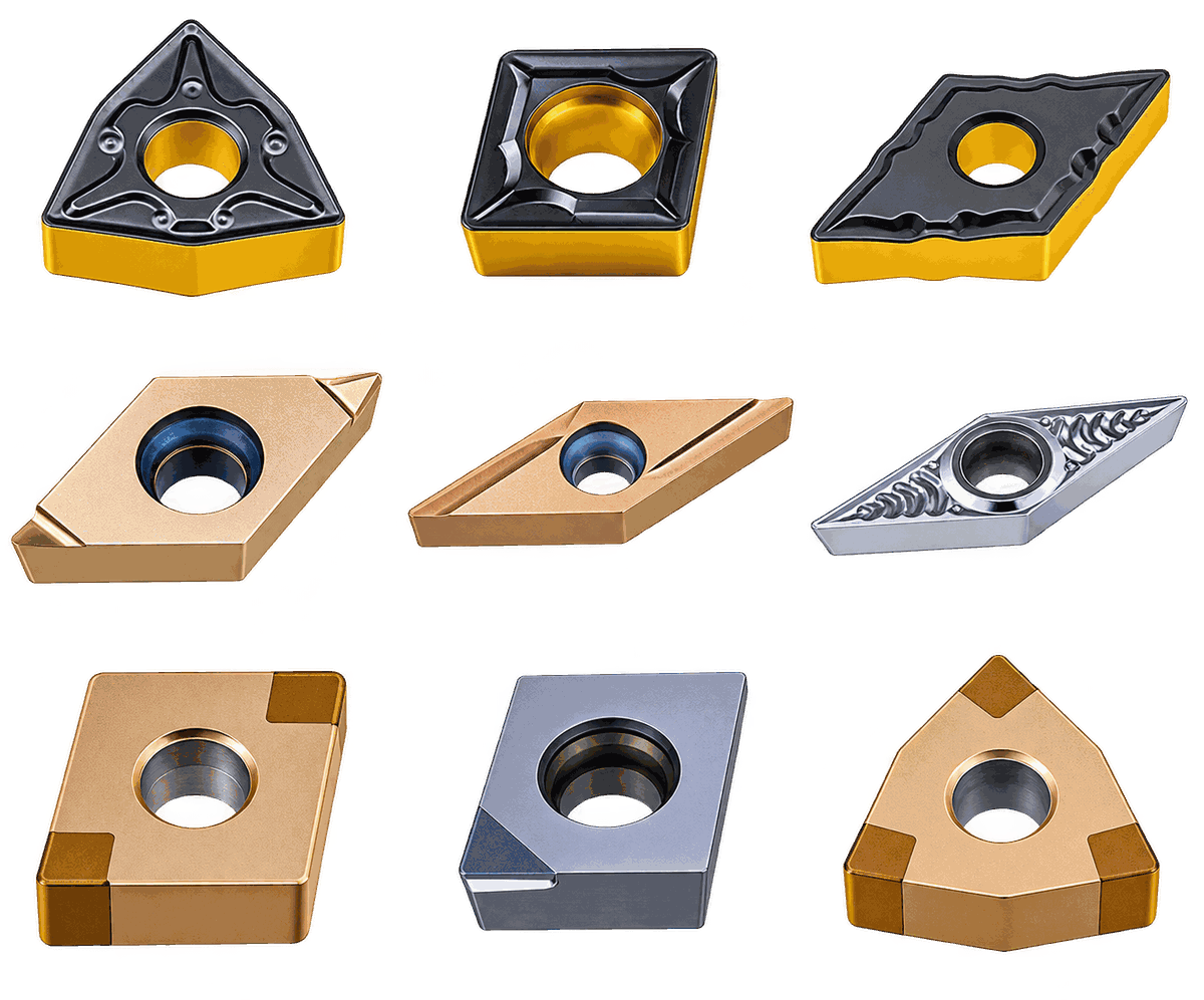
The insert is the only part of the tool that actually cuts. Everything else — the machine, the holder, the toolholder — merely keeps it at the right point in space. And it is not chosen by size: the size is set by ISO. It is chosen by two things you cannot see by eye — the chipbreaker geometry and the grade with its coating.
We reply within the working day. There is no minimum order.
Geometry
The most common mistake in selection is to start with the grade. In reality the first thing at work is the crater on the rake face: it sets how hard the insert enters the metal, how the chip curls and at what feed it finally breaks. The right grade with the wrong chipbreaker gives you “wire” on the tool block and a torn surface; the right chipbreaker with a mediocre grade works.
The logic of the designations is simple. The first letter is the application zone by depth of cut and feed: F — finishing, S — semi-finishing, M — medium, R — roughing, AX — non-ferrous metals. The second letter is the geometry variant within the zone. Tables of all 42 versions follow.
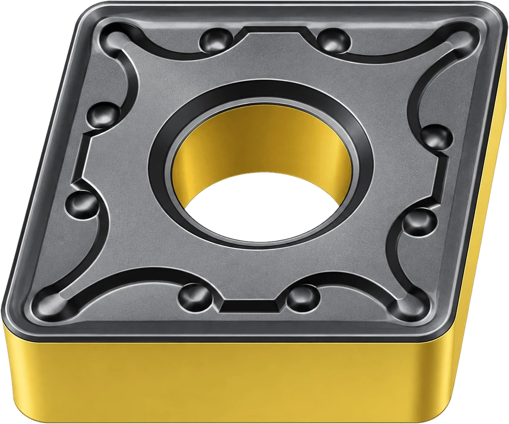
The side face stands at 90°: the insert can be turned over, and you get twice as many edges for the same price. The edge is stronger, because the metal under it is not cut away at an angle. The price is higher cutting forces, so a rigid part and a rigid machine are needed.
25 chipbreakers cover the range from finishing to heavy roughing.

Single-sided, with a sharper edge and sharply lower cutting forces. This is the choice for thin walls, long overhangs, small holes and non-ferrous metals — anywhere the part deflects or the machine will not hold.
23 chipbreakers, and almost two thirds of them in the finishing zone: that is exactly where a positive geometry gives an advantage.
Minimal cutting forces, a thin chip. Surface finish and accuracy matter more than productivity.
The finishing stock has already been taken off, the size is not final yet. The working zone for most parts.
The universal range. The most sought-after geometries in production work.
Scale, skin, heavy stock. A deep crater with a reinforced edge.
A polished sharp edge for aluminium, brass and bronze. A separate branch of the range.
The range
Twenty-five versions. The “Grades” column lists the grades this geometry is actually produced in: not every chipbreaker is available in every grade, and that is the most common reason why “the item you need is not available”.
| Chipbreaker | Zone | ISO insert shapes | Grades | Purpose |
|---|---|---|---|---|
| Finishing | ||||
| FM | Finishing | CNGGTNGGVNGGWNGG |
PM1775MS1385 |
The basic finishing crater on inserts with a lightened geometry. The lowest cutting forces among the negatives. |
| F | Finishing | TNGG |
K1775PM1775MS1385 |
The sharpest finishing geometry on a triangle. A mirror surface without grinding, cermet included. |
| FS | Finishing | VNGG |
KP1557MS2155PS2255 |
Finishing on a 35° rhombic — contour turning and copying, where access into a sharp corner is needed. |
| FA | Finishing | DNGX |
PS2255 |
A narrow geometry on a 55° rhombic for the universal PVD grade. |
| FB | Finishing | DNMG |
KP1557PM2557PS2255 |
Finishing with a reinforced edge: for when the surface has to be clean but the entry into the cut is not ideal. |
| Semi-finishing | ||||
| SM | Semi-finishing | CNMGTNMGTNGGWNMG |
KP1557PM2557MS2155PS2255 |
The lightest of the semi-finishing geometries. The working choice in stainless, where the point is to cut the metal rather than stroke it. |
| SE | Semi-finishing | CNMGSNMGTNMG |
KP1557PM2557MS2155PS2255 |
A wider crater, a higher feed. The working geometry for semi-finishing passes in steel. |
| SF | Semi-finishing | CNMGDNMGTNMGWNMG |
KP1557PM2557MS2155PS2255 |
The most widely used semi-finishing geometry: four insert shapes and four grades at once. |
| Medium machining | ||||
| MM | Medium | CNMGDNMGSNMGTNMGVNMGWNMG |
KP1557PM2557PM3557MS2155PS2255MP2575 |
The most universal item in the catalogue: six shapes, six grades. If a section keeps one box, this is the one. |
| MB | Medium | CNMG |
KP1557PM2557PS2255 |
A reinforced variant of the medium zone for uneven stock. |
| MH | Medium | CNMGSNMGVNMGWNMG |
K1775MP2575 |
A geometry for cermet and fine-grain PVD: medium machining with a requirement on surface quality. |
| MQ | Medium | CNMGSNMGWNMG |
K1775 |
The cermet series of the medium zone — where the chip must not stick to the edge. |
| MR | Medium | CNMGWNMG |
K1775 |
A variant of MQ with a modified crater profile for a higher feed. |
| MT | Medium | CNMGWNMG |
K1775 |
A cermet version for steel with higher demands on surface finish. |
| MY | Medium | WNMG |
K1775 |
A trigon in cermet: a rigid edge plus a clean surface. |
| MA | Medium | VNMG |
K1775 |
A 35° rhombic in cermet — contours with access into a sharp corner. |
| M2 | Medium | TNMG |
KP1557PM2557PM3557MS2155PS2255 |
A triangle across the full carbide line: from wear-resistant CVD to tough and PVD grades. |
| M3 | Medium | TNMG |
K1775 |
The cermet version of M2 for finishing passes. |
| M4 | Medium | TNMG |
K1775 |
A cermet triangle with a different crater profile for a higher feed. |
| Roughing | ||||
| RB | Roughing | CNMGTNMG |
KP1557PM2557PM3557PS2255 |
The basic roughing geometry: a deep crater, a reinforced edge, heavy stock. |
| RC | Roughing | CNMGDNMGSNMG |
KP1557PM2557PM3557PS2255 |
Three insert shapes — the widest coverage of roughing operations. |
| RD | Roughing | CNMGWNMG |
KP1557PM2557PM3557PS2255 |
Roughing for a trigon: a greater length of edge in the cut. |
| RH | Roughing | CNMGWNMG |
KP1557PM2557PS2255 |
A variant of RD with a different crater angle — for a softer chip. |
| RG | Roughing | VNMG |
KP1557PM2557PS2255 |
Roughing on a 35° rhombic: for when a contour has to be roughed out. |
| Non-ferrous metals | ||||
| AX | Non-ferrous | CNMGTNMGVNMGWNMG |
NN1070 |
A polished uncoated edge on a negative insert: aluminium and bronze with two working sides. |
The range
Twenty-three versions. The bias towards the finishing zone is not a whim of the catalogue but physics: a positive insert is made for light cutting and that is where it delivers what a negative one never will.
| Chipbreaker | Zone | ISO insert shapes | Grades | Purpose |
|---|---|---|---|---|
| Finishing | ||||
| F | Finishing | CCGTDCGTVBGT |
K1775PM1775MS1385 |
The sharpest finishing geometry in the line. Small parts, small stock, a surface finish requirement. |
| FM | Finishing | CCGTDCGTVCGT |
PM1775MS1385 |
A universal finishing geometry on an ultra-fine-grain substrate: it holds size right through the batch. |
| FL | Finishing | CCGTVCGT |
PM1775MS1385 |
A lightened variant of FM for even lower cutting forces — thin walls and non-rigid parts. |
| FP | Finishing | VCGT |
PS1255 |
Finishing on a 35° rhombic with a wear-resistant PVD grade: heat-resistant alloys and titanium. |
| FS | Finishing | CCGTSCGTTCGTVCGT |
PS1255 |
The widest finishing range by shape. The working geometry for hardened steel and nickel alloys at light cutting data. |
| FB | Finishing | RCMT |
PS2255 |
A round insert: copy turning and large-radius fillets. |
| J | Finishing | DCGT |
PM1775MS1385 |
A special crater on a 55° rhombic for small parts on automatics. Right-hand version only. |
| U | Finishing | CCGTDCGT |
K1775PM1775MS1385NN1070 |
A universal finishing geometry, available at once in cermet, PVD and uncoated grades — one geometry for different materials. |
| W | Finishing | CCGTDCGT |
PM1775MS1385 |
A version of U with a different crater profile for a wider feed range. |
| Q | Finishing | VBGT |
K1775PM1775MS1385NN1070 |
A 35° rhombic for Swiss-type lathes: four grades, nose radii from 0.05 mm. |
| X | Finishing | DCETVBETVCET |
PS1255 |
The “E” series — an ultra-sharp edge for small precision parts. Right- and left-hand versions. |
| Y | Finishing | DCETTBGTVBETVCET |
PS1255PS2255 |
The same class as X, but with a reinforced edge — for when the ultra-sharp one starts to chip. |
| Semi-finishing | ||||
| SE | Semi-finishing | SCMTTCMT |
PM2557PS2255 |
The transition from finishing to medium on a square and a triangle. |
| SQ | Semi-finishing | CCMTDCMTVBMT |
K1775 |
Cermet semi-finishing in three shapes — finishing passes in steel without grinding. |
| ST | Semi-finishing | VBMT |
K1775 |
Cermet on a 35° rhombic: contours with a mirror surface. |
| Medium machining | ||||
| MP | Medium | CCMTDCMTTPMT |
K1775 |
The widest cermet item: three shapes, medium cutting data, a stable surface. |
| MF | Medium | CCMTSCMTTCMTTPMH |
PM2557MS2155PS2255 |
The main working item of the positive medium zone: four shapes, three universal grades. |
| ME | Medium | CCMTSCMTVBMT |
PM2557PM3557MS2155PS2255 |
The only positive chipbreaker available in a tough CVD grade — medium machining with light impact. |
| MG | Medium | CCMTTCMT |
PM2557MS2155PS2255MP2575 |
A variant of MF, extended with fine-grain PVD for stainless. |
| MC | Medium | CCMTVCMT |
MP2575 |
A dedicated stainless item: a fine grain plus a heat-resistant coating. |
| MK | Medium | VCMT |
MP2575 |
The same on a 35° rhombic — contours in stainless. |
| Non-ferrous metals | ||||
| AX | Non-ferrous | CCGTDCGTRCGTSCGTTCGTVBGTVCGT |
NN1070 |
Seven insert shapes with a polished uncoated edge. The main aluminium series. |
| AX4 | Non-ferrous | CCGTDCGTSCGTTCGTVCGT |
NN1050 |
The same geometry in a grade with a diamond-like layer — against the abrasive silicon in high-silicon aluminium. |
A separate case — the flat rake face. In cast iron the chip breaks up on its own, and a chipbreaker crater only weakens the edge. So the programme includes inserts with no chipbreaker at all — with a flat rake face: solid metal under the edge, so it takes the impact of the scale. CBN and PCD inserts of the CNGA, DNGA, TNGA, WNGA, VNGA and SNGA series are made the same way, with no crater.
Grades
A grade designation can be read without a reference book. The first letters are the ISO 513 groups it was created for: PM — steel and stainless, PS — steel and heat-resistant alloys, MS — stainless and heat-resistant alloys, NN — non-ferrous metals, K — cermet, C — CBN, D — polycrystalline diamond. Then come the application figures and the coating technology code.
The mark in a cell says not “suitable or not” but what kind of cutting the grade will take in that material: continuous, with slight interruptions, or fully interrupted.
| Grade | Technology | PSteel | MStainless | KIron | NNon-fer. | SHeat-res. | HHardened | Where this works |
|---|---|---|---|---|---|---|---|---|
| Cermet with a PVD coating | ||||||||
| K177592,5–93,5 HRA | Cermet + PVD | ● | – | – | – | – | – | Finish turning of steel where a mirror surface is needed without grinding. Cermet is less tough than carbide, so continuous cutting only, with no impact. The widest cermet range in the line: MQ, MR, MT, MY, MA, M3, M4, MP, SQ, ST. |
| Carbide with a multilayer CVD coating | ||||||||
| KP1557wear-resistant | CVD · TiCN–Al₂O₃–TiN | ○ | ○ | ● | – | – | ○ | The first recommendation for cast iron. Finishing and semi-finishing, continuous cutting, dry and wet. A thick Al₂O₃ layer holds the temperature — grey iron can be run at high speed. |
| PM2557universal | CVD · TiCN–Al₂O₃–TiN | ● | ● | ● | – | – | – | The most widely used grade in the programme and the first recommendation for alloy steel. Semi-finishing and medium machining, slight interruptions. The case where a section keeps one box for all its parts. |
| PP2577gradient substrate | CVD · TiCN–Al₂O₃–TiN | ● | – | – | – | – | – | A substrate with hardness varying through the section: hard on the outside, tough inside. Steel and cast steel from finishing to roughing, continuous and lightly interrupted cutting. Cast iron at low and medium speeds. |
| PM3557tough | CVD · TiCN–Al₂O₃–TiN | ■ | ■ | □ | – | – | – | The toughest CVD grade in the line and the first recommendation for roughing stainless. Medium machining and roughing with impact: scale, skin, eccentrics, castings. The only grade rated for fully interrupted cutting of cast iron. |
| Carbide with a PVD coating | ||||||||
| PS1255wear-resistant | PVD · AlTiSiN | ● | ○ | ● | – | ● | ○ | Finishing in continuous cutting. A thin PVD coating does not blunt the edge — which is why this grade is the one used on titanium, nickel alloys and hardened steel at light cutting data. An anti-corrosion layer: the insert does not bloom in the store or in the emulsion. |
| PM177593,5–94 HRA | PVD on an ultra-fine 0.3–0.4 µm grain | ● | ● | – | – | – | – | Finishing of stainless, cast iron and steel. An ultra-fine grain gives the rare combination of high hardness with impact toughness — the edge holds both the size and the occasional impact. The coating has a violet tint. |
| MS138593,5–94 HRA | PVD on an ultra-fine 0.3–0.4 µm grain | ● | ● | – | – | ● | – | The same substrate, a different coating — black. Finishing of stainless and heat-resistant alloys, including thin-walled parts where low cutting forces matter. |
| MS2155anti-adhesion | PVD · AlTiXN + ZrN | ○ | ● | ○ | – | ● | – | Its speciality is difficult-to-machine materials. A ZrN layer resists adhesion: in stainless and heat-resistant alloys the edge dies not from wear but from a built-up edge that tears away and takes carbide with it. Semi-finishing and medium machining, wet. |
| PS2255universal PVD | PVD · AlTiSiN | ● | ● | ● | – | ● | – | The workhorse of the PVD line: four ISO groups out of one box. Semi-finishing and medium machining of carbon and alloy steel, stainless and heat-resistant alloys. It will take light interrupted cutting. |
| MP2575fine grain | PVD on a fine-grain substrate | – | ● | – | – | – | – | A narrow speciality: finishing of various stainless steels at medium and low speeds, when a strong edge and high surface quality are needed at the same time. High heat resistance, takes light interruptions. The coating colour is a dark blue-grey. |
| Carbide uncoated and with a diamond-like layer | ||||||||
| NN1070submicron grain | Uncoated | – | – | – | ● | – | – | Non-ferrous metals. A submicron grain allows the edge to be ground sharper than any coating permits — and aluminium is cut precisely by sharpness. Chipbreakers AX, U, Q; continuous and interrupted finish turning. |
| NN1050diamond-like layer | CVD · Diamond-like | – | – | – | ● | – | – | Aluminium alloys, including high-silicon alloys that eat ordinary carbide within a dozen parts. Cast wheels, housings, finishing and medium machining. The AX4 chipbreaker in five insert shapes. |
| Superhard materials | ||||||||
| D1370polycrystalline diamond | PCD | – | – | – | ● | – | – | For when the life of a carbide insert in aluminium is measured not in parts but in minutes. Ten times the price, a hundred times the life. Continuous cutting only, non-ferrous metals and non-metals only. |
| C1370cubic boron nitride | CBN | – | – | ○ | – | – | ● | Turning instead of grinding. Hardened steel HRC 45–65, hard facing, chilled cast iron. It removes an operation from the cycle: the part leaves the machine already to size and with the required finish. |
| C1155CBN with a PVD layer | CBN + PVD | – | – | ○ | – | – | ● | The same CBN plus PVD on top: the coating reduces friction and extends life over long passes in hardened steel. The version for production runs, when one edge has to last to the end of the batch. |
The matrix shows the character of cutting the grade will take in that material, not “suitable or not”. An empty cell does not mean the grade physically cannot cut that material — it means there is a better grade in the programme for that job.
Coating
A coating a few microns thick gives a bigger gain in tool life than any change of substrate composition. But there is no single “good” coating: what saves the edge in cast iron at high speed will come off in stainless within a minute, and in aluminium it only gets in the way. That is why the KARASAWA programme has not one coating but eight different technologies — and that is exactly where the breadth of the range comes from.
The difference between CVD and PVD is not marketing but physics. CVD is deposited at 900–1000 °C: the layer comes out thick, multilayer, with an interlayer of aluminium oxide acting as a thermal barrier. Such a layer takes high speeds, but the edge under it is slightly rounded. PVD is applied at 400–500 °C: the layer is thin, the edge stays sharp, and there are compressive stresses that hold it against chipping. Hence the split: CVD for speed and heat, PVD for sharpness and impact toughness.
| Technology | Colour | Grades | What it does in the cut |
|---|---|---|---|
| CVDTiCN–Al₂O₃–TiN, multilayer | gold top layer | KP1557PM2557PM3557 |
A thick layer with aluminium oxide inside — a thermal barrier. It takes high cutting speeds and dry machining. The base for steel, cast steel and cast iron. The TiN top layer is gold not for looks: worn-through gold shows at a glance which edge has already been used. |
| Gradient CVDsubstrate with varying hardness | black and yellow | PP2577 |
Not the coating itself but the substrate under it: hard on the outside, tough at the core. The insert is wear-resistant and not brittle at the same time — which is why one grade covers the range from finishing to roughing in steel. |
| PVD AlTiSiNwear-resistant, corrosion-resistant | grey steel | PS1255PS2255 |
The silicon in it forms a dense, oxidation-resistant film on the surface. The thin layer does not eat into the sharpness of the edge — hence its use on titanium, nickel alloys and thin walls. Corrosion resistance matters outside the cut too: the insert does not deteriorate in a wet emulsion or in the store. |
| PVD AlTiXN + ZrNanti-adhesion | light brass | MS2155 |
The top layer of zirconium nitride has a low affinity for austenitic steel and nickel. That strikes directly at the main cause of edge failure in these materials — a built-up edge that tears away together with a grain of carbide. |
| PVD on an ultra-fine grain0.3–0.4 µm, 93.5–94 HRA | violet, black | PM1775MS1385 |
What works here is not so much the layer as what is under it. A grain several times finer than usual gives 94 HRA hardness and high transverse rupture strength at the same time — a combination out of reach for a standard substrate. An insert for finishing operations with tight requirements on size. |
| PVD on a fine grainheat-resistant | dark blue-grey | MP2575 |
High resistance to thermal shock — the kind that arises in interrupted cutting with flood coolant, when the edge goes through a heat-cool cycle every second. Finishing stainless at medium and low speeds. |
| PVD on cermetTiC–TiN substrate | light grey | K1775 |
Cermet has a naturally lower affinity for steel than tungsten-cobalt carbide: the chip does not stick and the surface comes out mirror-like. The coating adds wear resistance without taking that property away. The price is low toughness: cermet does not forgive impact. |
| Diamond-like CVDdiamond-like | dark grey | NN1050 |
Against the abrasive silicon in high-silicon aluminium. Ordinary carbide in such alloys wears away like chalk — a diamond-like layer pushes that limit back by an order of magnitude. |
| Uncoatedsubmicron grain | polished carbide | NN1070 |
Sometimes the best coating is no coating. Any layer rounds the edge by a few microns; in aluminium, copper and plastics that is enough to turn cutting into crushing. A polished uncoated edge cuts cleanly and produces no built-up edge. |
| PCD and CBNsuperhard materials | white, black | D1370C1370C1155 |
Not a coating but a separate cutting material brazed onto a carbide substrate. PCD is for non-ferrous metals and composites, CBN for hardened steel and chilled cast iron. Both replace a grinding operation, not an insert. |
Coating colour is not decoration but a working tool for the operator. It tells the grade apart in an unlabelled box and shows how worn the edge is: a worn-through layer is visible to the naked eye before any instrument shows the size going out.
In summary
The difference between a cheap insert and the right one shows not on the invoice but on the thirtieth part: when one is still holding size and the other has already taken the batch out of tolerance. Three things that show it in advance.
An ultra-fine-grain substrate, controlled hardness, a ground periphery. The next box of the same grade behaves like the last one — the program does not have to be adjusted after every delivery. That is the main thing we promise, and the main thing that can be checked.
Forty-two chipbreaker geometries across sixteen grades are not there for the catalogue. It means you will not have to put a “steel” crater into stainless or a coated insert into aluminium. Every machining zone is covered not by one compromise version but by several, for different insert shapes.
The sizes are to ISO, so the insert fits an existing toolholder from any manufacturer. The grade designation reads off the first letters. The application matrix is published, not “available from your account manager on request”. Selection takes a minute, not an exchange of e-mails.